Why Do I Want To Do This?
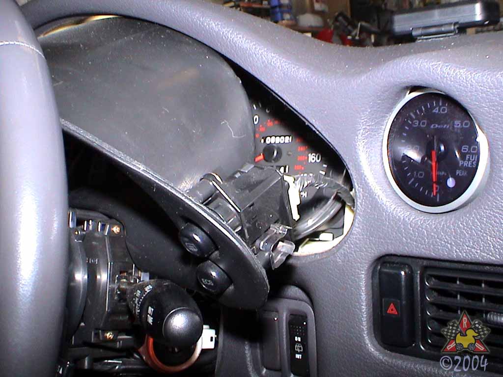
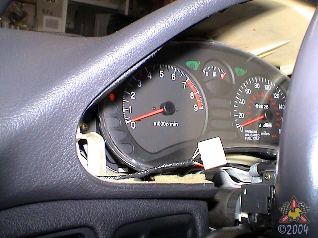
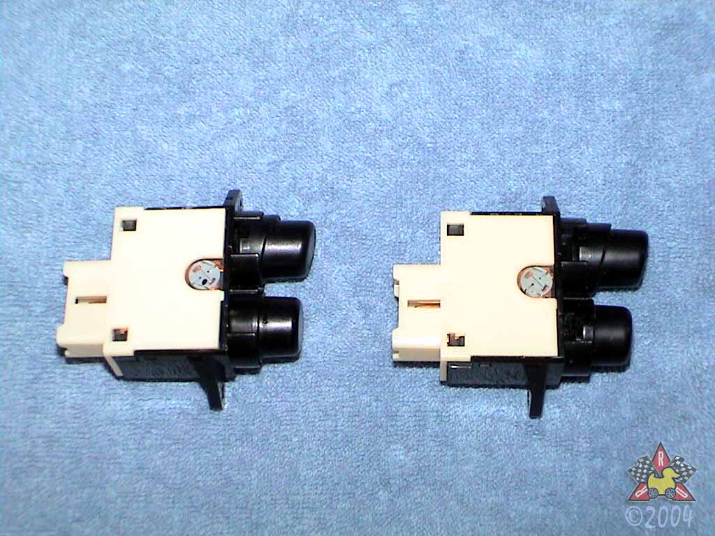
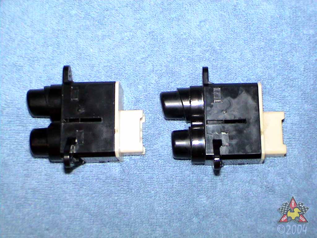
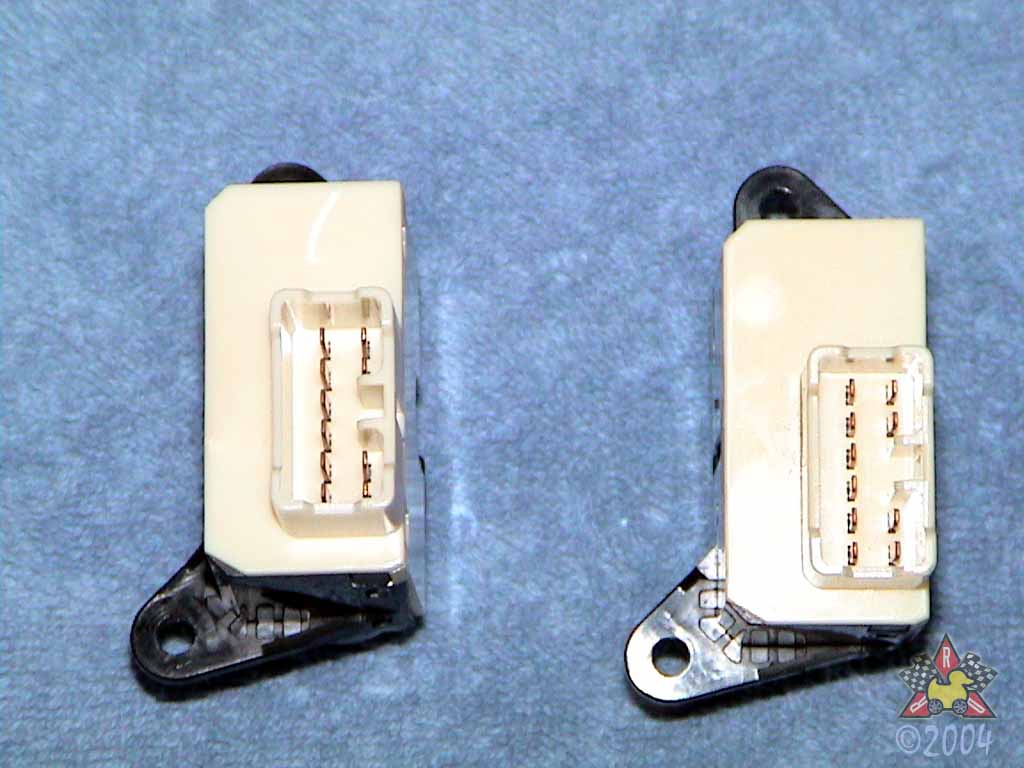
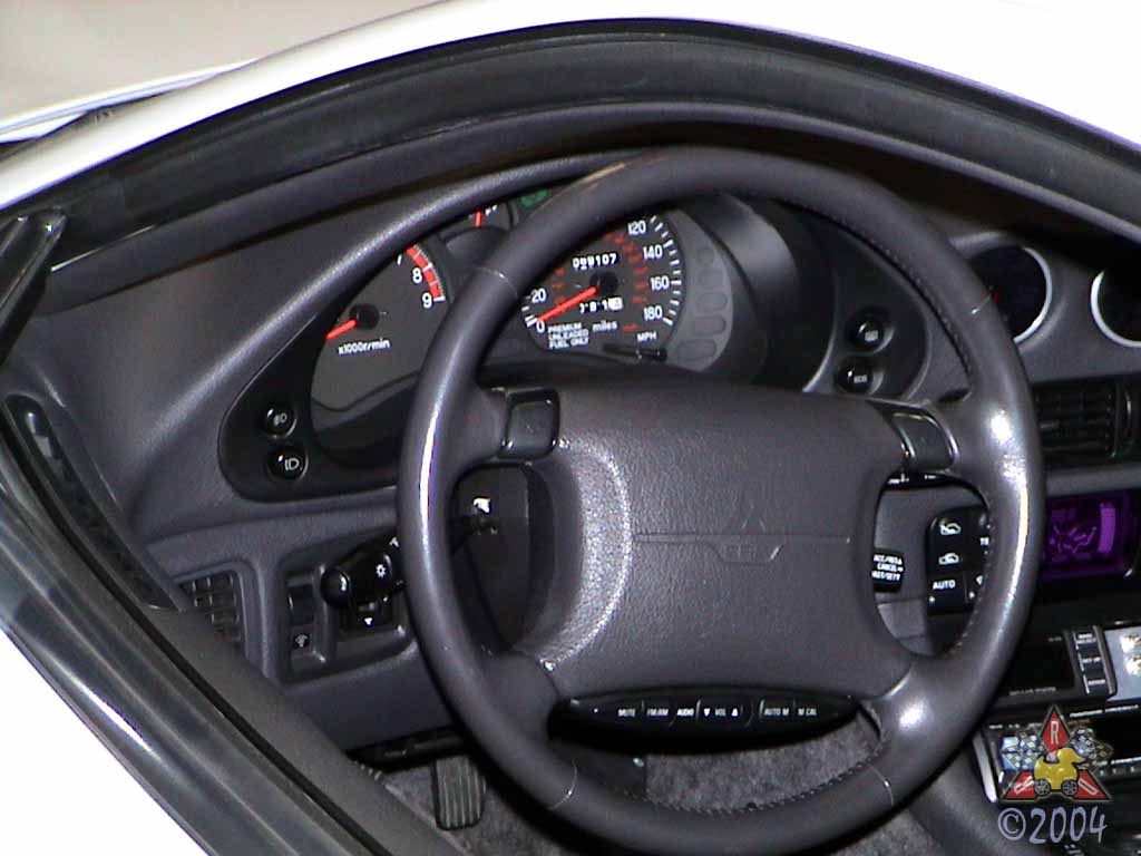
- If you need a switch to control a device you added to your car and you want to keep the OEM look, this modification is for you. The OEM popup switch is a DPST switch where all 3 terminals are unconnected in the '94+ cars.
- I used this switch to provide the lighting signal to all of my aftermarket devices. Many of the electronic devices I have installed in my car have an input for an illumination wire; this wire lets the device know when the car's headlights are on, and the device dims its lighting for nighttime operation. I found that the nighttime lighting mode of my aftermarket electronics made it difficult to read them at dusk or when driving with my headlights on during the day. Thus, I wanted a way to interrupt the illumination signal to the aftermarket devices if I wanted to. Essentially, I wanted to be able to have my headlights on and have my aftermarket electronics operate at full brightness. This switch allows me to do this.
How Long Will It Take Me To Do This?
- Plan on an hour or two so you're not hurried.
Anything I Should Do Prior To Attempting This Procedure?
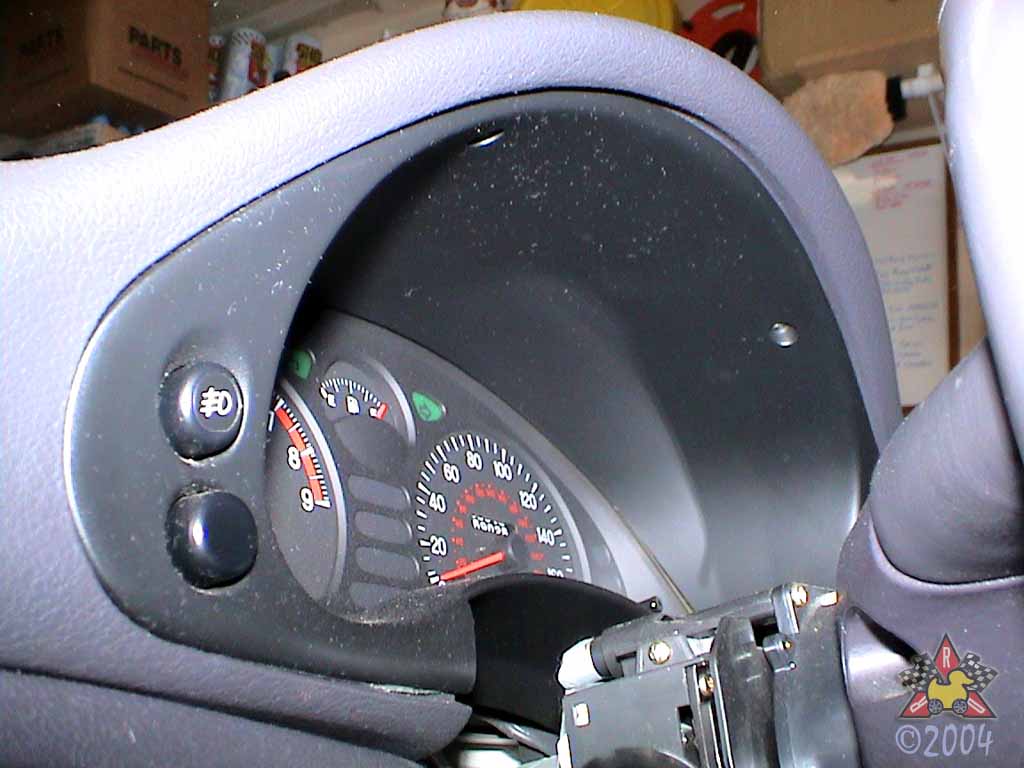
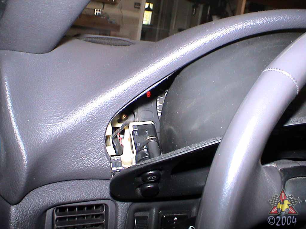
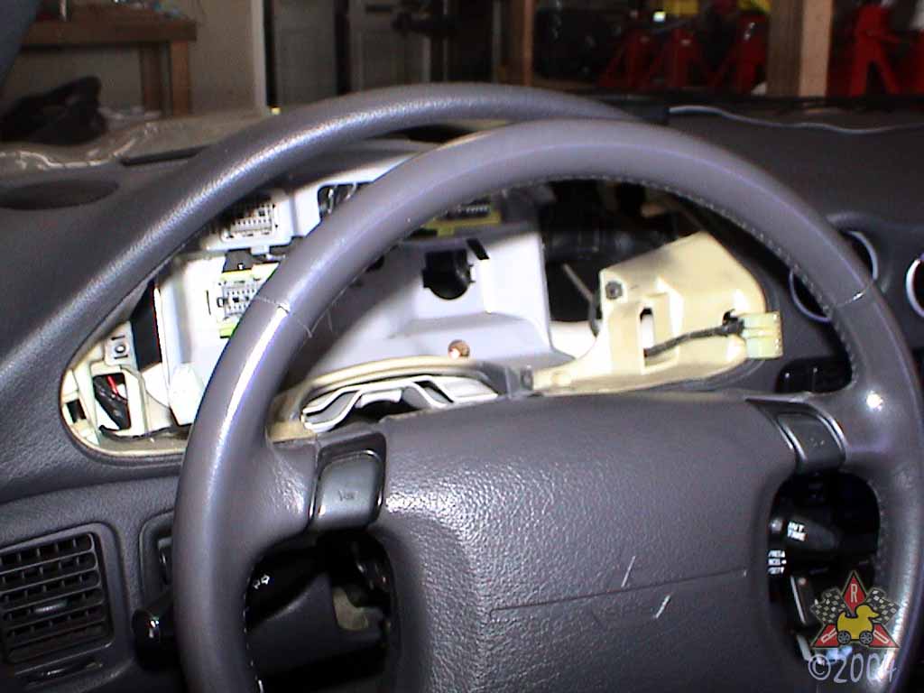
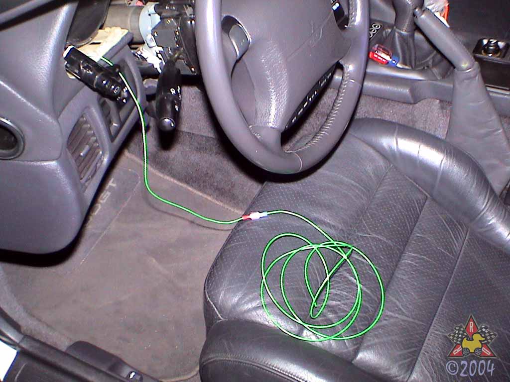
- You may want to remove the plastic cover for the steering column to give you some extra room to maneuver. There are 4 screws on the bottom, some clips in the middle, and then it just pops off in upper and lower halves.
What Mitsubishi Parts Will I Need?
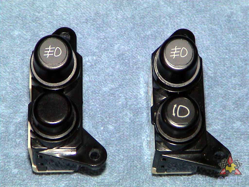
- (1) MB604770 ($35.00) Headlight Popup Combination Switch (from '91-'93 models)
What Other Parts Will I Need?
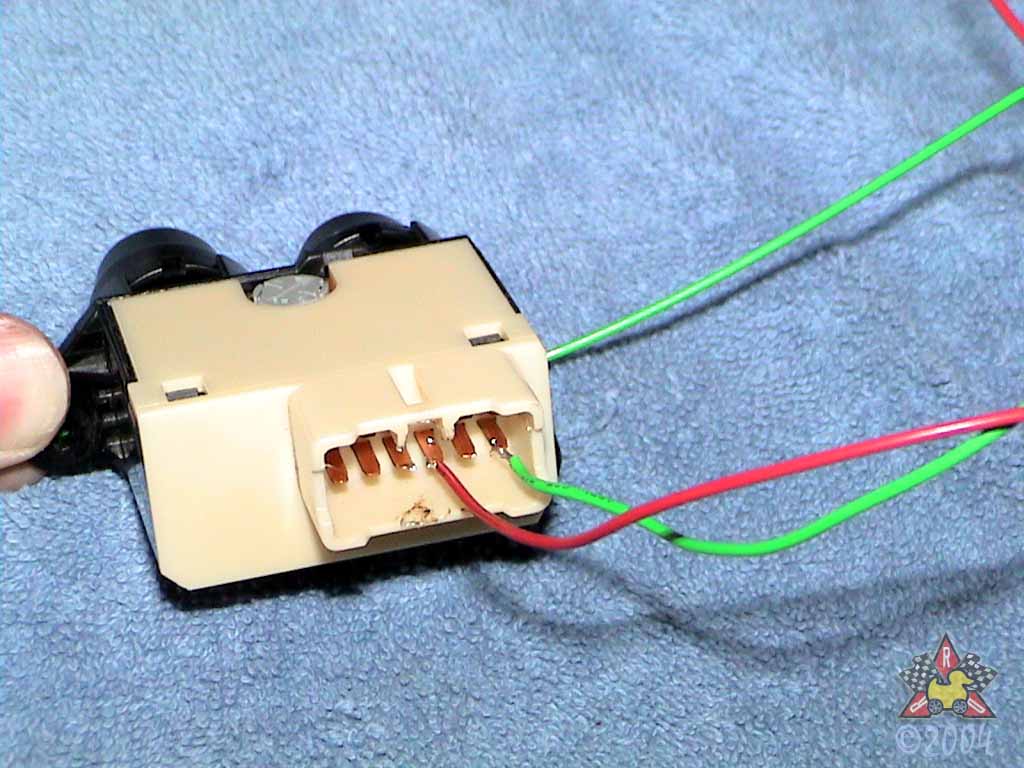
- Misc 18ga wire
- Solder
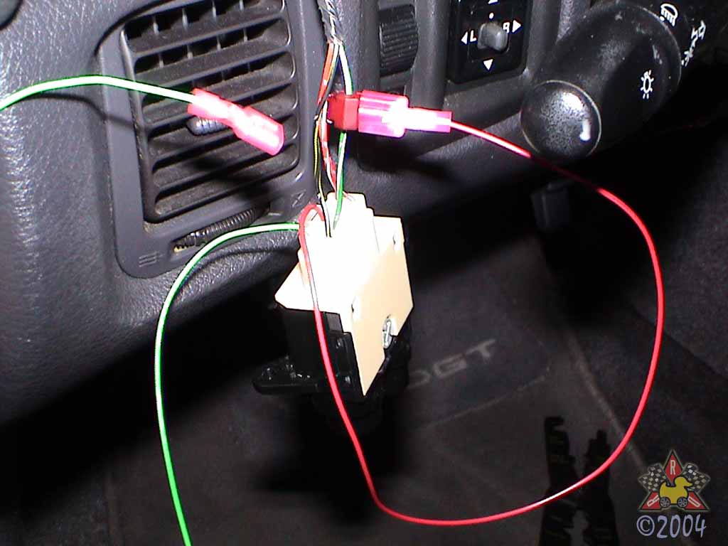
- [optional] T-taps and quick-disconnect connectors
Where Can I Get the Stuff To Do This?
| Part | Company/Contact | Part Number | |
|---|---|---|---|
|
|
Headlight Popup Combination Switch (from '91-'93 models) |
Mike Deal at Rockville Mitsubishi |
MB604770 |
|
|
Misc. 18ga wire | McMaster-Carr | |
|
|
T-taps and quick-disconnect connectors | McMaster-Carr | |
|
|
Solder | Radio Shack |
What Tools May/Will I Need?
- #2 Philips Screwdriver
- Large Slotted Screwdriver
- Soldering Iron
- Pliers
Erik's Review
- I'm completely happy with this modification and I've had zero issues with it since installation. I really like being able to adjust the brightness of my instrumentation when the car's lights are on. I also really like having the OEM switch, even if it's not labeled correctly, as it doesn't stand out from the rest of the interior.