|
Remove the Radio Trim
|
|
|
|
|
|
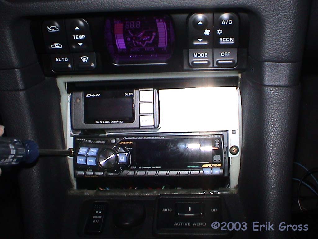
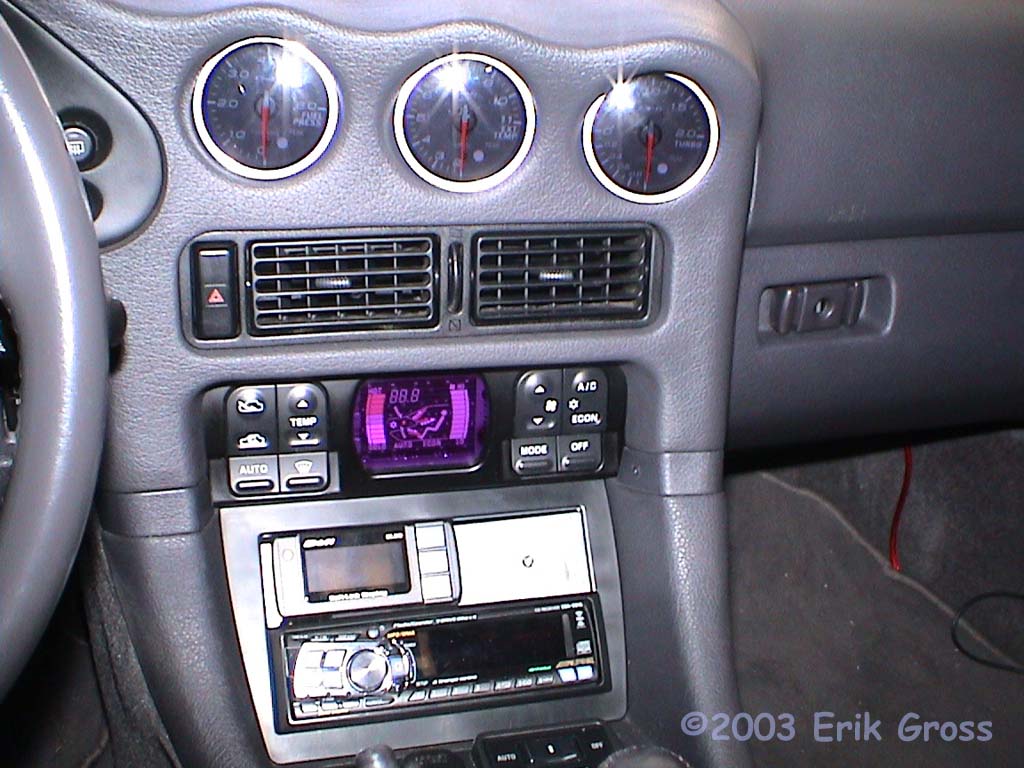
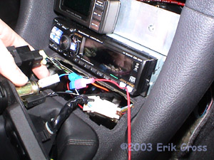
Remove the trim ring from around the radio by gently prying it loose
with a small slotted screwdriver.
|
|
|
|
Remove the Radio
|
|
|
|
|
|
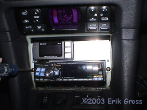
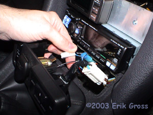
Remove the 4 Philips screws that secure the head unit assembly. I only have 2
in the picture because I'm in the process of custom mounting some accessories
above the radio.
|
|
|
|
SWI-X Parts
|
|
|
|
|
|
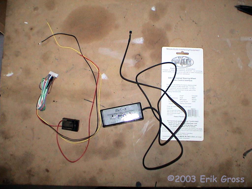
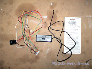
Examine the parts that came with your SWI-X. You should have the SWI-X control box,
the wiring harness, and a bezel for the LED (usually attached to the LED).
|
|
|
|
Bundle Wires You Aren't Going To Connect
|
|
|

|
|
|
You're only going to need the red, black, and yellow wires for this installation, so
coil up the other wires and secure them with a zip tie.
|
|
|
|
Attach Connectors To Wires
|
|
|
|
|
|
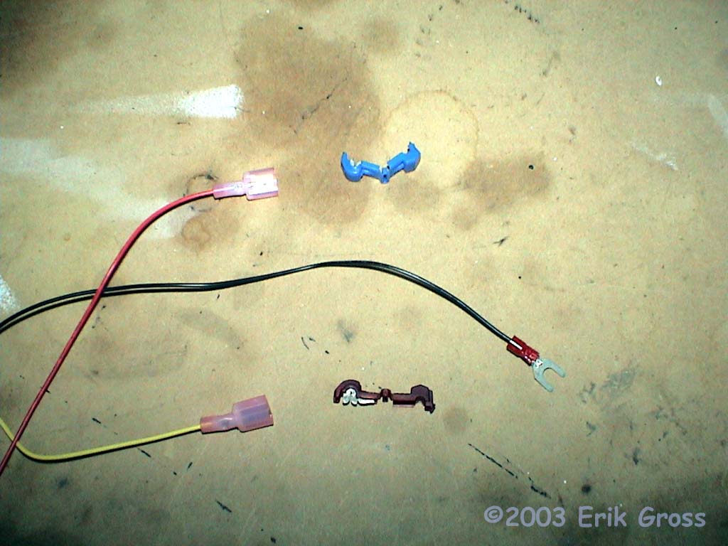
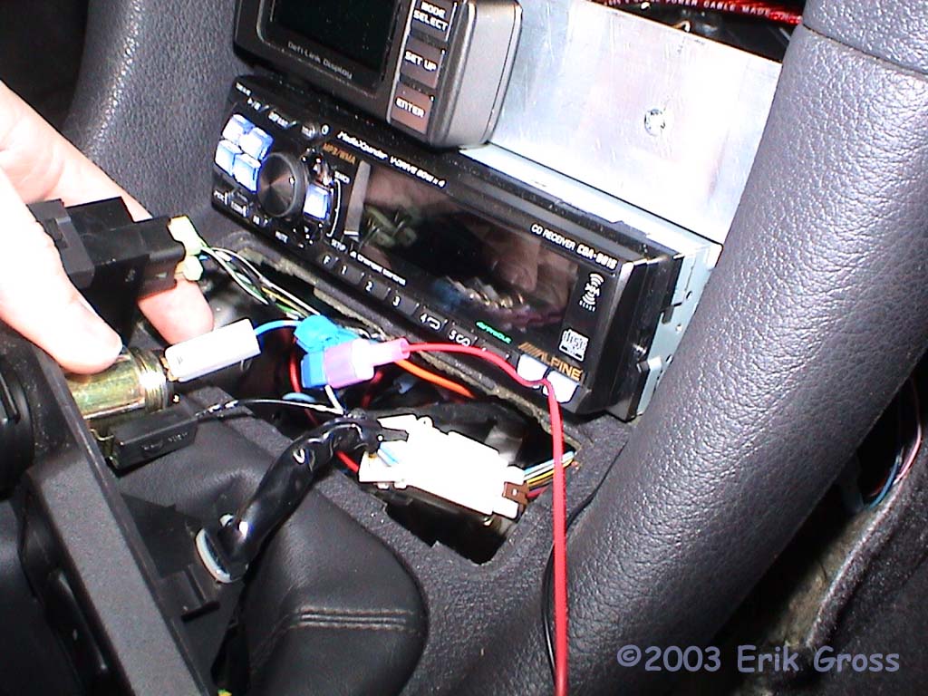
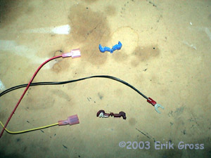
Attach your crimp-on connectors to the ends of the red, black, and yellow wires. Depending
on how you decide to connect your wires, you may want to do this step differently. Since
I connected the black (ground) wire directly to a grounding screw, I used a spade connector.
Since I used T-taps for the power (red) and signal (yellow) wires, I attached male quick
disconnect fittings to those wires.
|
|
|
|
Connect Ground Wire
|
|
|
|
|
|
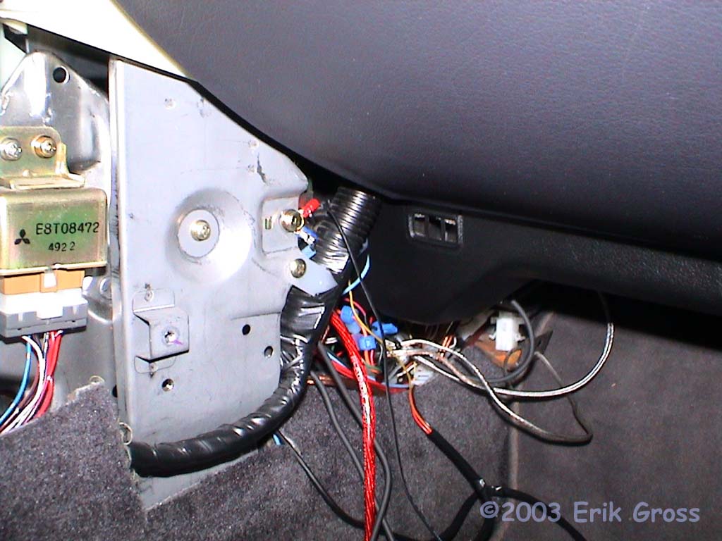
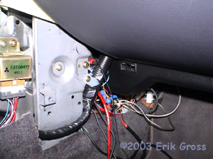
Connect the black (ground) wire to a ground location. I used the existing grounding
screw on the passenger's side of the radio near the glovebox.
|
|
|
|
Find Power Source
|
|
|
|
|
|
Decide on a switched +12V power source for the SWI-X. Typically, you want an ACC wire,
and not an IGN wire so that the SWI-X is always powered when the radio is powered. I used
the power lead from the accessory outlet directly below the radio. Other convenient
options are the cigarette ligher power supply and the switched radio power supply. I
disconnected the power supply from the power outlet to get some extra slack in the wire,
but you don't have to do this. T-taps work by crimping them around the existing wire - you
may find pliers useful. Also, I used a blue (14-16ga) T-tap for this application because
the wire size for the power outlet is 16ga. If you use another wire that is 18ga or
smaller, you'll want to use a red T-tap.
|
|
|
|
Connect Power Wire
|
|
|
|
|
|
Plug the red (power) wire into the installed T-tap to connect power to the SWI-X.
|
|
|
|
Find OEM Steering Wheel Signal Wire
|
|
|
|
|
|
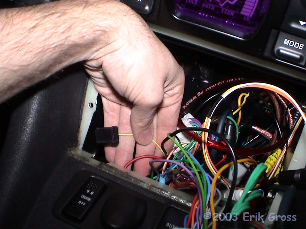
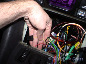
Fish around behind the radio and find the small 6-pin black harness that used to
connect to the stock stereo. It should only have one wire attached to it and the wire
is yellow.
|
|
|
|
Connect Serial Data Wire
|
|
|
|
|
|
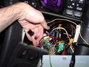
Connect a red (18-22ga) T-tap to the yellow OEM wire and then connect the yellow
SWI-X wire to the T-tap. The OEM yellow wire is the serial data wire for the stock
steering wheel radio controls and is what will "tell" the SWI-X when you press
a steering-wheel button, as well as which one you pushed.
|
|
|
|
Program the SWI-X
|
|
|
|
|
|
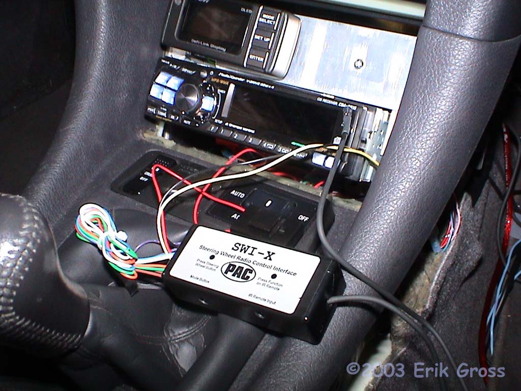
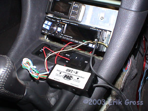
Now that all 3 of the electrical connections have been made, position the radio back
in its normal location so that you can program the SWI-X. You need to have the
SWI-X control box accessible for the programming procedure, so don't stuff it into
the nether regions of the dash yet. Follow the programming procedures in the SWI-X
manual.
Some suggestions:
- I found that the IR Extended Mode seems to work a little better
- The Firmware mode number for all 3000GTs and Stealths is #5
- Make sure you program all 6 steering wheel buttons in the same programming
"session" or you'll only have the most recently programmed functions.
- As you program the SWI-X, don't hold any of the buttons down for more
than 1 second or so; when I did that, I didn't get a clean signal.
- Turn off all fluorescent lighting anywhere near your car while
programming the unit. I had some lighting on on the other end of my
garage and it still generated enought IR interference that the SWI-X
didn't program correctly.
- The programming I settled on was to have the following functions
programmed into the 6 factory steering wheel buttons (left to right):
Play/Pause; Source; Vol(-); Vol(+); Track(-); Track(+)
|
|
|
|
Test-Mount the IR LED (optional)
|
|
|
|
|
|
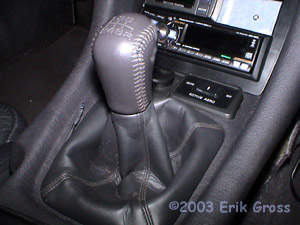
At this point, you may want to temporarily mount the SWI-X's IR LED so that it's
pointed in the general direction of the stereo. Since I was experimenting with
LED locations, I chose to mount it here (beside the shifter) for a day of driving
to make sure it worked. If you're mounting it in the location I ended up with,
you can probably skip this step.
|
|
|
|
Remove Trim and Drill Hole
|
|
|
|
|
|
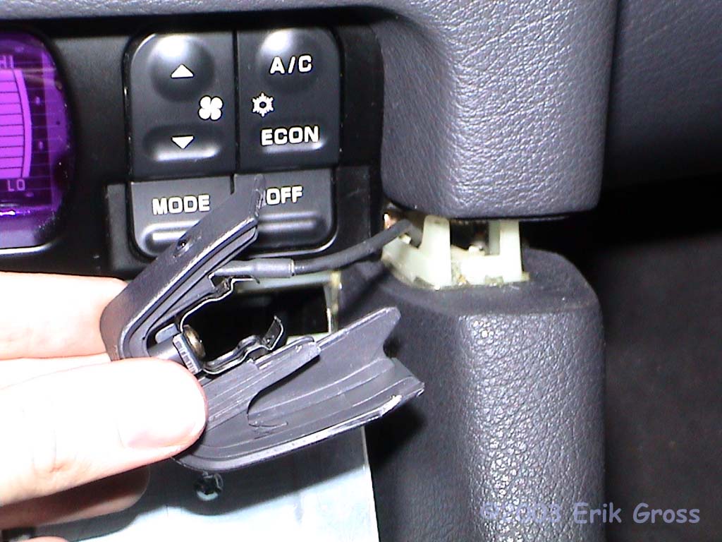
Now comes the mounting of the LED part. It's gotta be somewhere that allows the
output (light) of the LED to hit the receiver part of your aftermarket stereo.
Depending on your particular stereo and the layout of your interior, this location
may or may not work for you. I'd think it would work for most people, though.
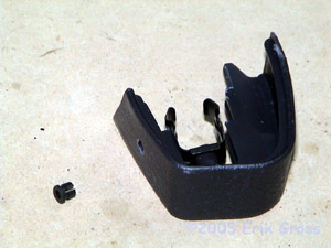
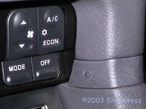
Pull off the trim piece on the right side of the center console to the right of the
climate controls. Just wiggle it until it pops out - it should be pretty easy. Remove
the screw that hold the retaining clip to the back so that you can remove the clip and
have room to cleanly drill the hole for the LED. Using your 13/64" drill bit, carefully
drill a hole in the trim piece. LED bezel (removed from LED) shown to the left.
|
|
|
|
Mount LED in Trim Piece
|
|
|

|
|
|
Once you've drilled your hole and cleaned it up, you need to route the LED through
the maze under the dash and have it come out the hole behind the trim piece. Make
sure you have it come out the SIDE hole and not the front hole, or you won't
be able to get the trim piece back on. Push the LED through the back side of the trim piece,
attach the bezel to the LED, and then push the bezel/LED assembly back into the hole.
It should be a tight, but reasonable fit. Bend the leads on the LED to get them
out of the way of the clip. And put the clip/screw back on if you haven't
already done that :-)
|
|
|
|
Replace Trim Piece
|
|
|
|
|
|
Replace the trim piece in its former location, being careful not to damage the
LED's wires.
|
|
|
|
Done
|
|
|
|
|
|
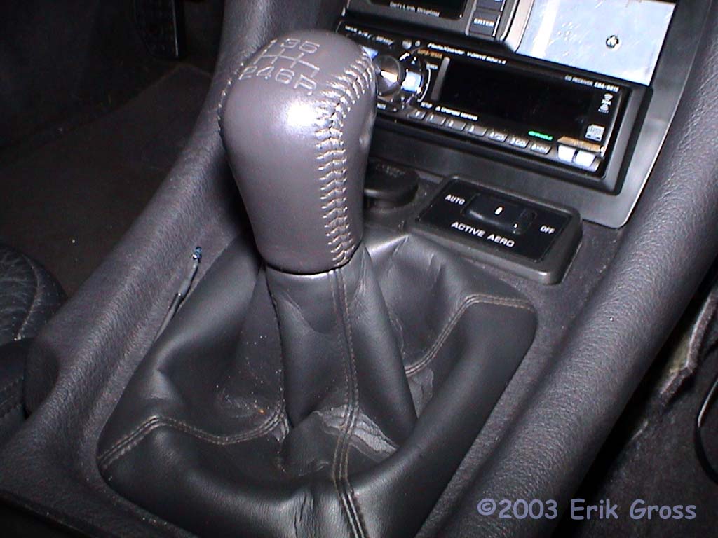
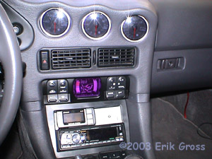
All done. You really can't see it unless there's a lot of light and you know where
to look.
|
|