|
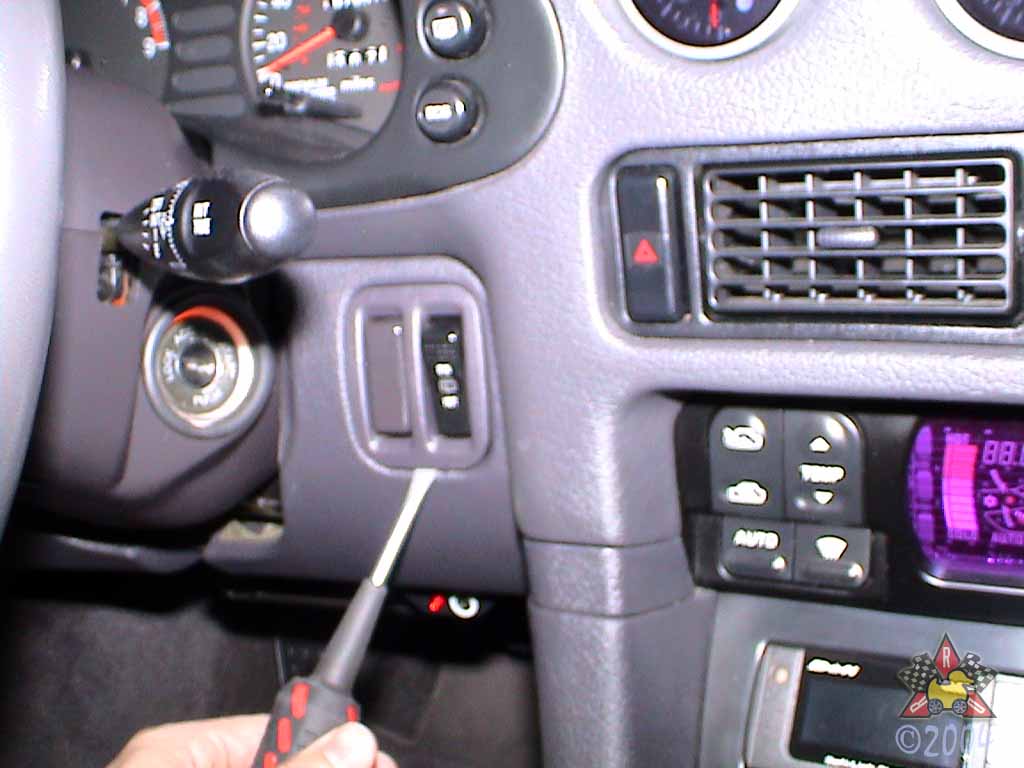
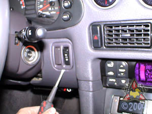
Pull Switch Assembly Out of Dash
|
|
|
|
|
|
Insert a screwdriver under the trim and gently pry it away from the dash.
|
|
|
|
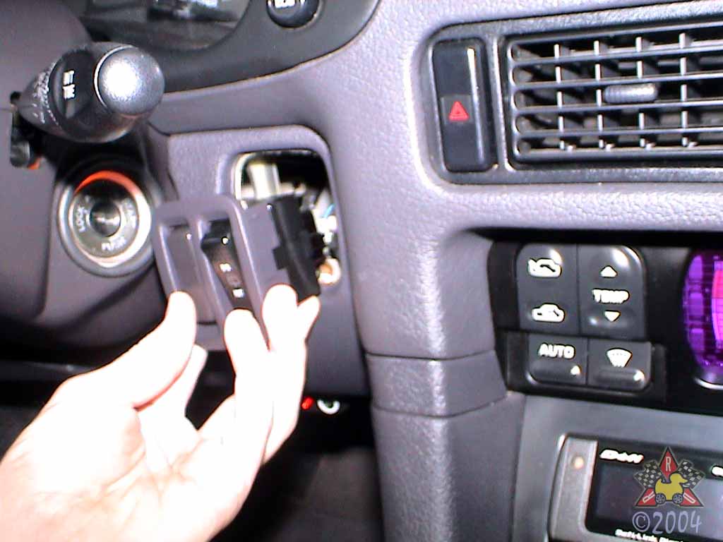
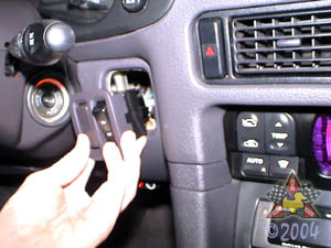
Remove Switch Assembly
|
|
|
|
|
|
Disconnect the wiring harness from the back of the switch and
move the switch assembly out of the way.
|
|
|
|
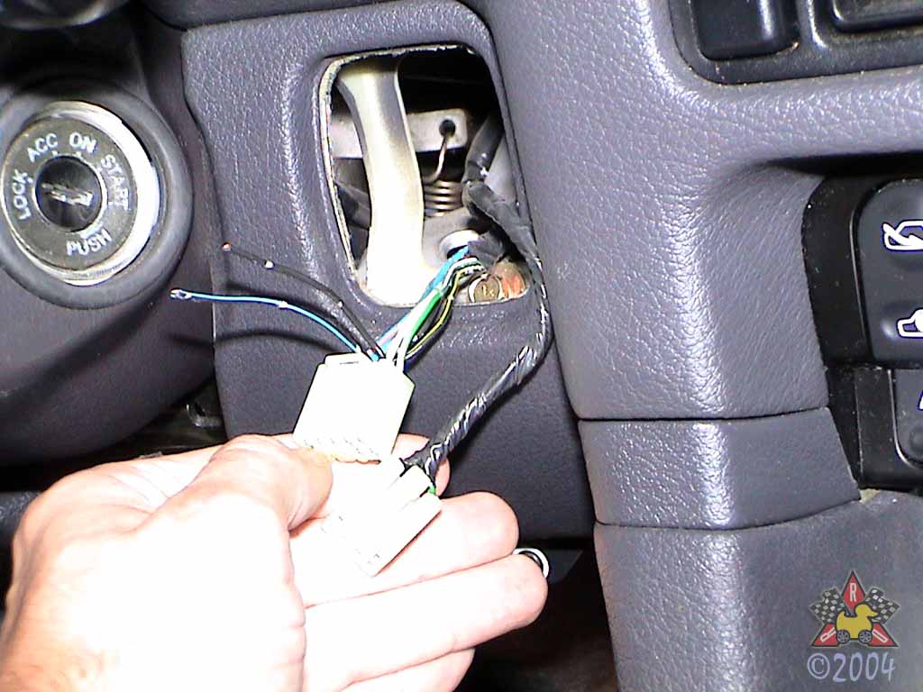
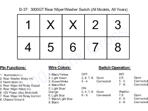
Identify Wires
|
|
|
|
|
|
Figure out which wires you'd like to use and cut them away from the
OEM wiring bundle if necessary. I chose to use wires 7 and 8
(black and black/light blue) because they are only used for the
rear wiper's intermittent function, which I never use. This leaves
me with a switch that still operates the rear wiper (ON mode only)
and the rear washer, but allows me to connect an extra component
to the switch. Since I wanted to use the switch to control my water
injection system and I wanted the WI system to operate with the
key in both the ACC and ON positions, I simply connected the wire
I cut from Pin 7 to the wire for Pin 6 (Light Blue), which is an ACC
power wire. This leaves the wire I cut from Pin 8 (black) available for
connection to the WI system.
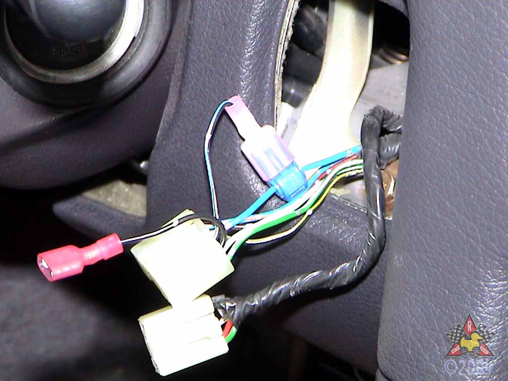
To summarize, wire connected to Pin 8 will
be disconnected when the switch is in the OFF or ON positions. The rear wiper
will operate normally as far as the OFF and ON positions are concerned. Also,
the washer pump will work normally. When the
switch is turned to the INT position, it will now apply 12V power to the wire
connected to Pin 8, which will provide power to my Water Injection system.
Further, when the switch is in the INT position, there will be no power to
the rear wiper motor or washer pump.
|
|
|
|
Cut Wires From Harness
|
|
|
|
|
|
For my particular application, I needed to cut the wires connected to pins 7 and 8
in the washer switch harness. These wires are the black wire and the black wire
with the light blue stripe.
|
|
|
|
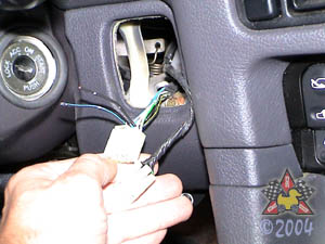
Attach Wires To New Location(s)
|
|
|

|
|
|
I attached a t-tap to the light blue wire connected to Pin 6
and then connected the cut end of Pin 7 to this t-tap. I then attached
a quick-disconnect connector (red) to the cut wire connected to Pin 8.
The red connector in the picture is the wire that will provide power to
my WI system. It is unconnected when the switch is in the OFF or ON
position and has 12V power when the switch is in the INT position.
|
|