|
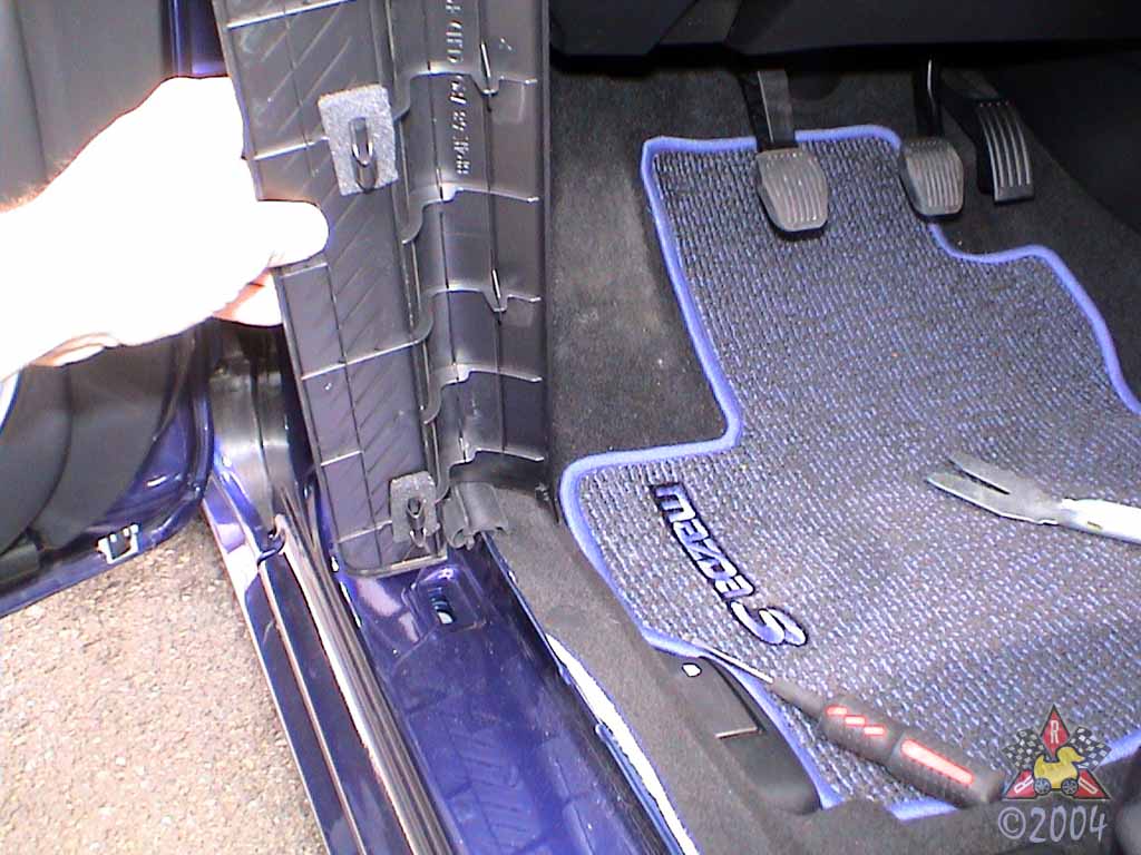
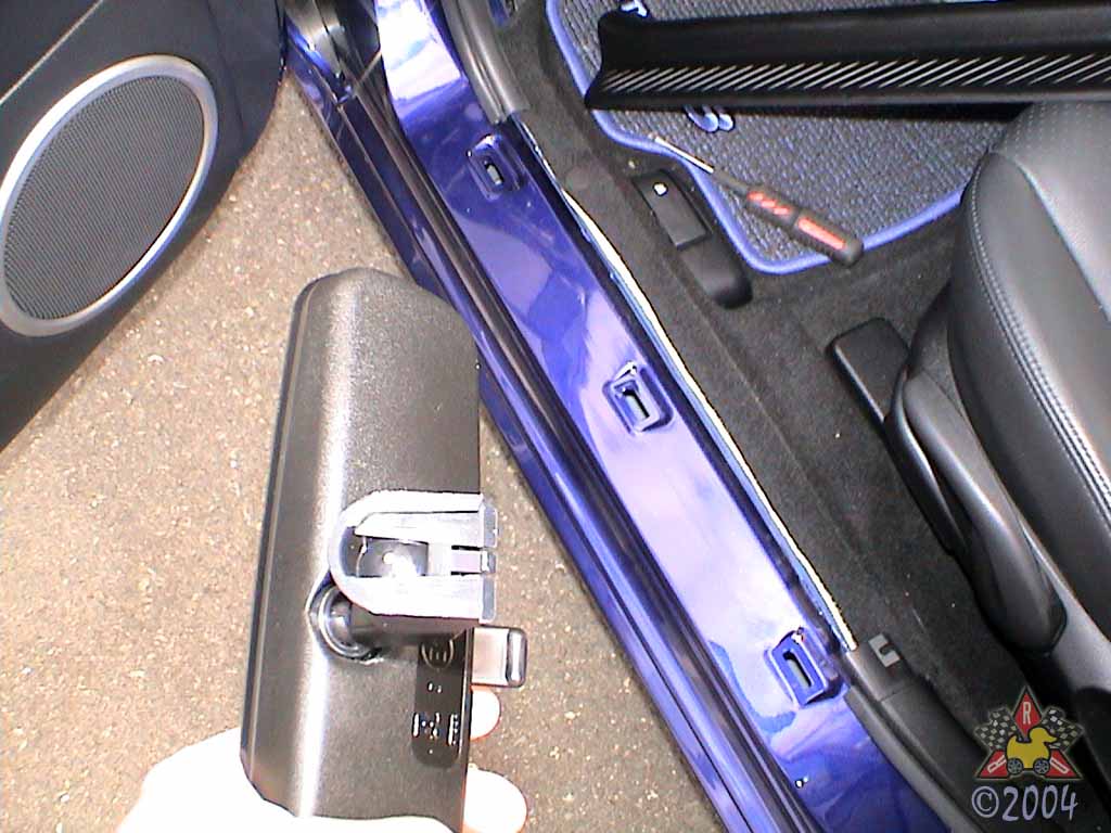
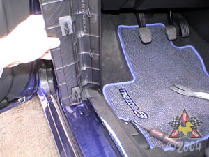
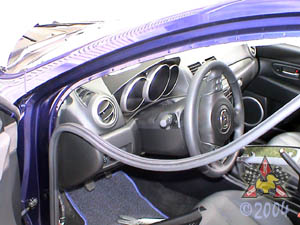
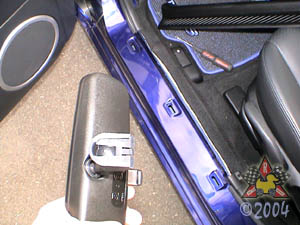
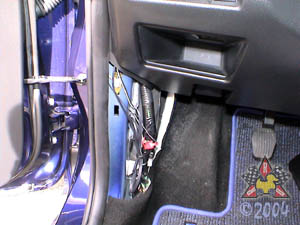
Remove Driver's Side Scuff Plate and Kick Panel
|
|
|
|
|
|
There are little clips that hold the trim in place. Carefully
pry the whole thing upwards and it'll just pop out. Use a trim
panel tool if you have one, but a screwdriver will work just as well.
For the kick panel (trim to the left of the clutch pedal), there's just
one plastic fastener to remove and then it just pops off. To remove the
plastic fastener, insert your small flat-blade screwdriver under the
center section to pry it up. Once the center section is unlocked,
pull the fastener out.
|
|
|
|
Partially Remove Door Weatherstripping
|
|
|
|
|
|
Just grab it and gently pull it away from the chassis. You
only need to remove enough of it to access the a-pillar trim
and the driver's side kick panel.
|
|
|
|
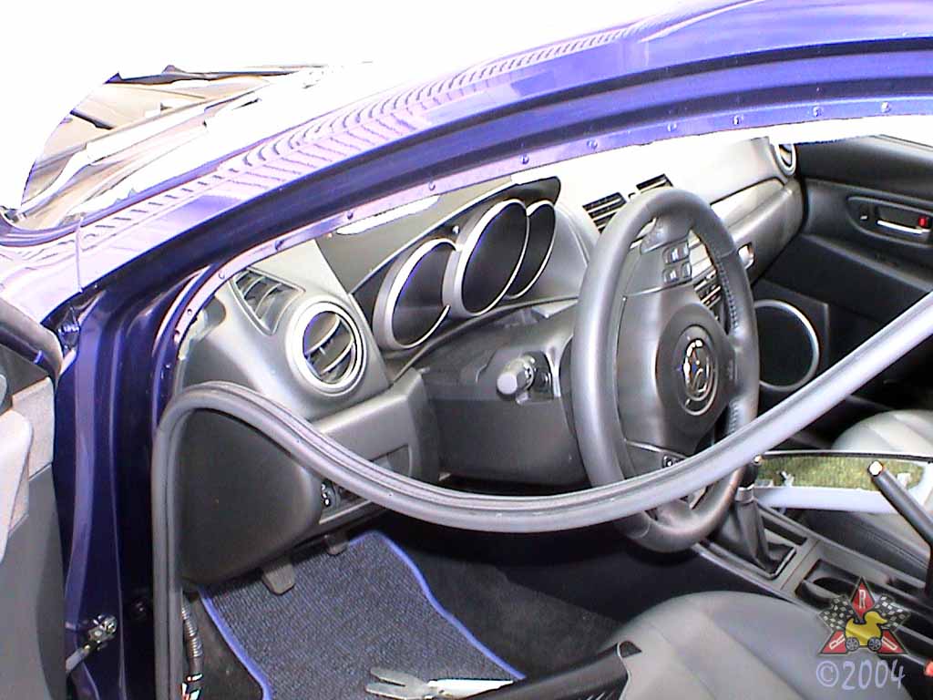
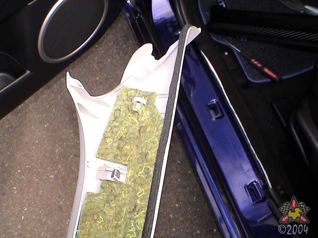
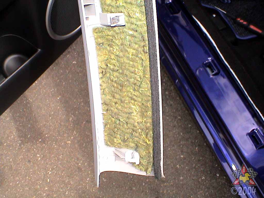
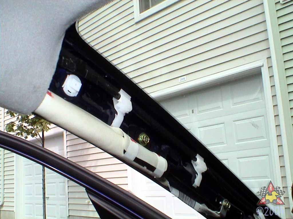
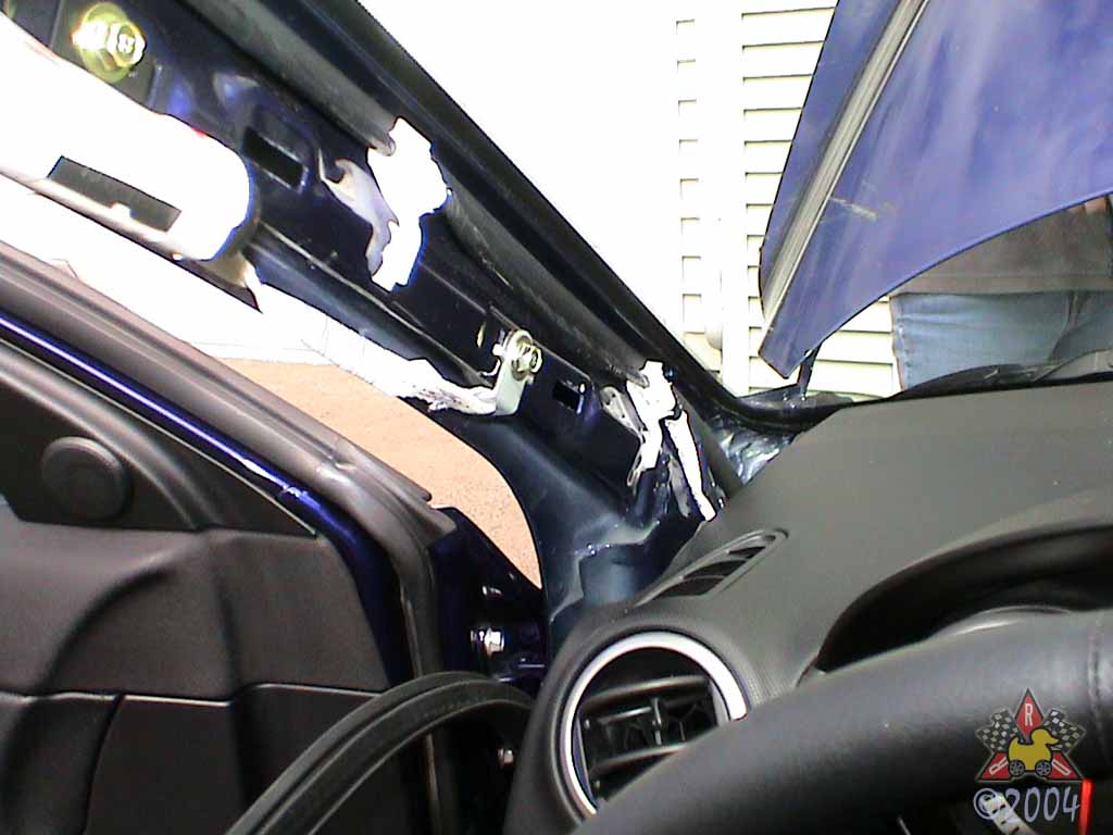
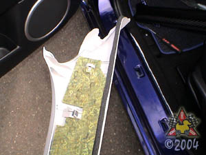
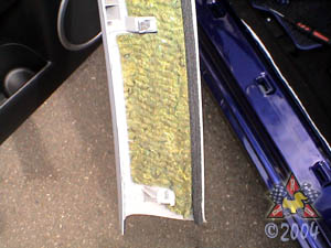
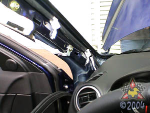
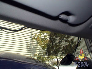
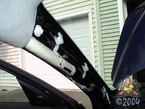
Remove Driver's Side A-Pillar Trim
|
|
|
|
|
|
The lower and middle fasteners will just pop loose as you pry the
trim toward the passenger's side of the car. The upper fastener
will not pop loose if you just pull on it. You need to loosen the
lower two fasteners and then slide the whole thing along the A-pillar
toward the roof to clear the upper fastener. Be careful of
the side air curtain if you have one - don't poke a hole in it
or move anything in its way.
|
|
|
|
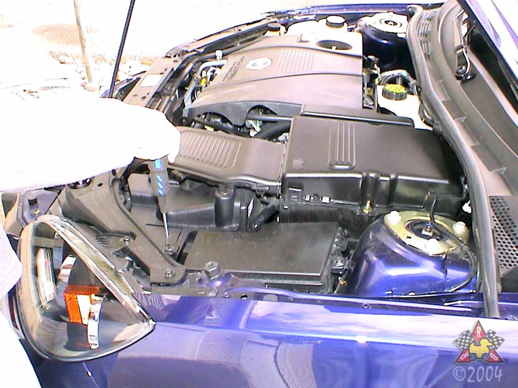
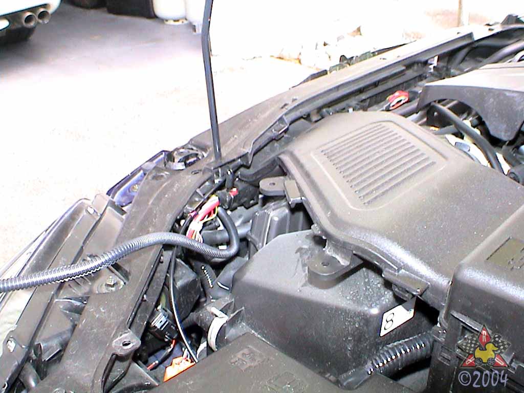
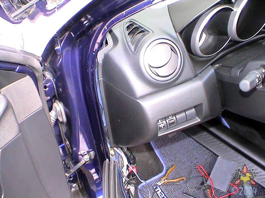
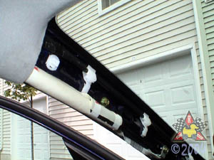
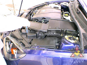
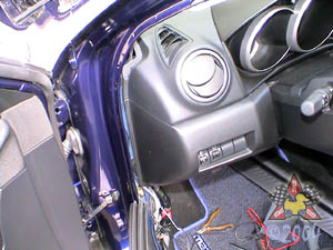
Remove Plastic Cover Near Airbox
|
|
|
|
|
|
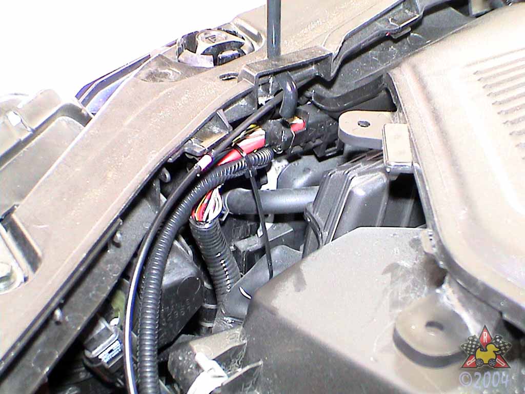
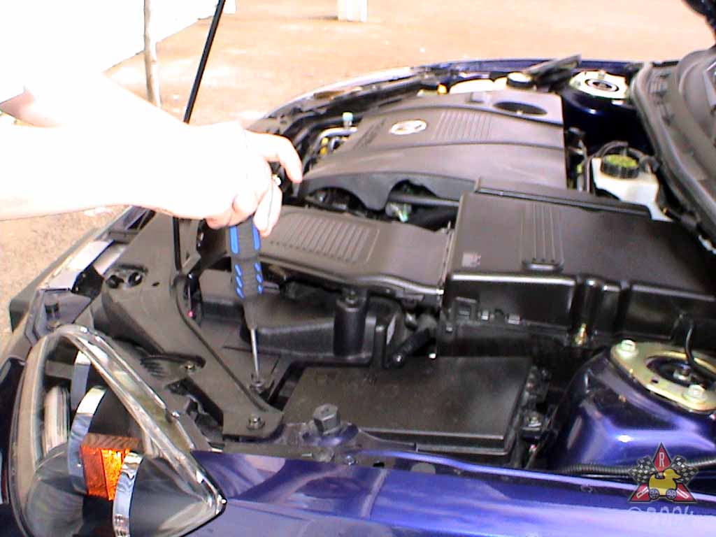
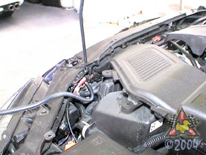
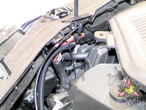
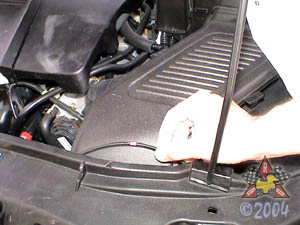
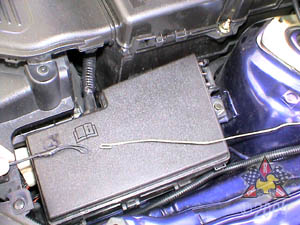
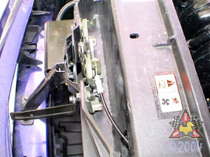
There's a little plastic cover held in place by three plastic
screw-type fasteners as shown in the picture. Remove the fasteners
by unscrewing the center section and then prying the rest of
the fastener out of the hole. The reason for removing this
panel is so you have access to where you need to run the
wires for the temperature sensor.
|
|
|
|
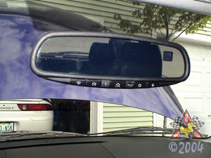
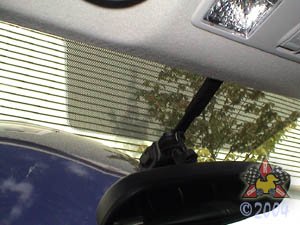
Remove OEM Mirror
|
|
|
|
|
|
There's a little tab on the bottom that clips it into
place - lift the tab and push the whole assembly upwards.
Mine was a little stuck, so I used a screwdriver and a
rubber mallet to carefully tap the mirror free while I
held the tab up. That worked ok, but be careful not
to get carried away with the mallet!
|
|
|
|
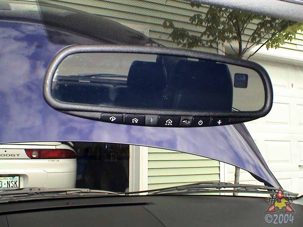
Install Mirror
|
|
|
|
|
|
It slides right on and then is secured with an #20 Torx (star) screw. Tightening torque
is 1.3 ft*lbs, so "barely snug" should do.
|
|
|
|
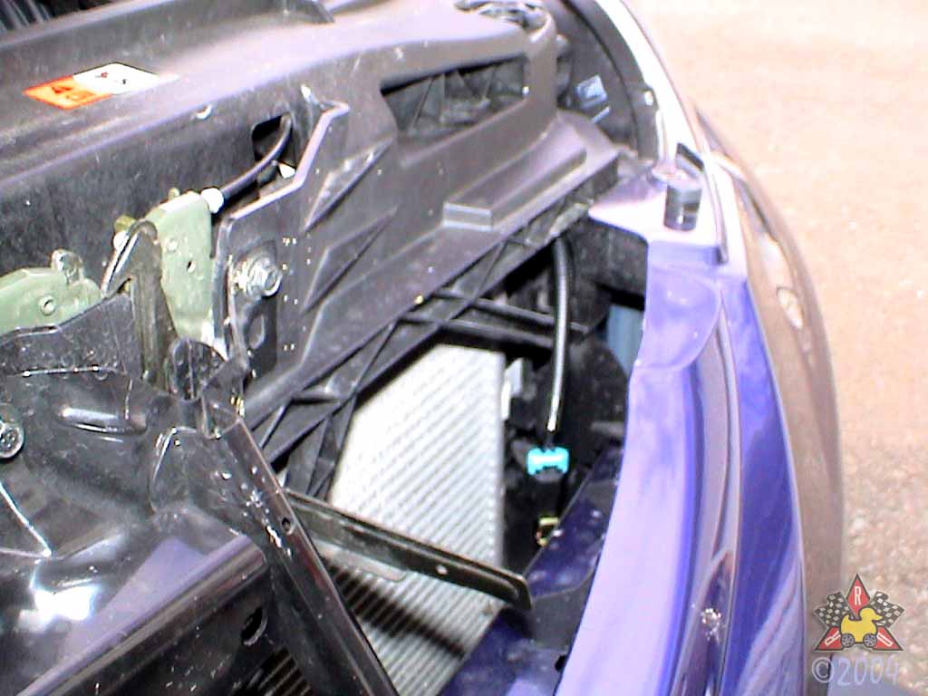
Route Temperature Sensor Toward Radiator
|
|
|
|
|
|
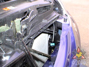
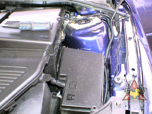
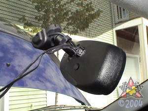
Thread the temperature sensor through the area shown so that you can get it
near the front of the radiator. Hang on to the other end of the wire so it
doesn't all fall down there!
|
|
|
|
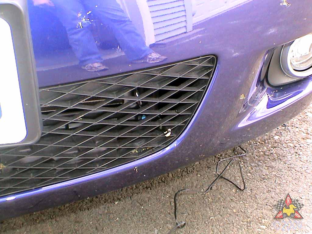
Secure Temperature Sensor To Grill
|
|
|
|
|
|
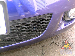
Clip it onto the grill as shown. Wiggle it around to make
sure it's securely attach and won't be blown off by wind.
|
|
|
|
Secure Wiring Near Radiator
|
|
|
|
|
|
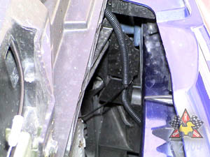
Use a couple of zip ties (provided by Mazda) to secure the
wiring as you run it up near the radiator and toward the
fuse box.
|
|
|
|
Route Wire Along Fender
|
|
|
|
|
|
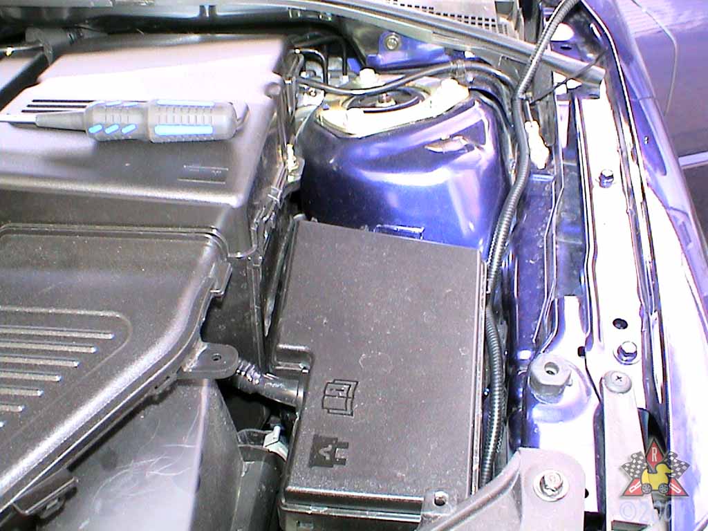
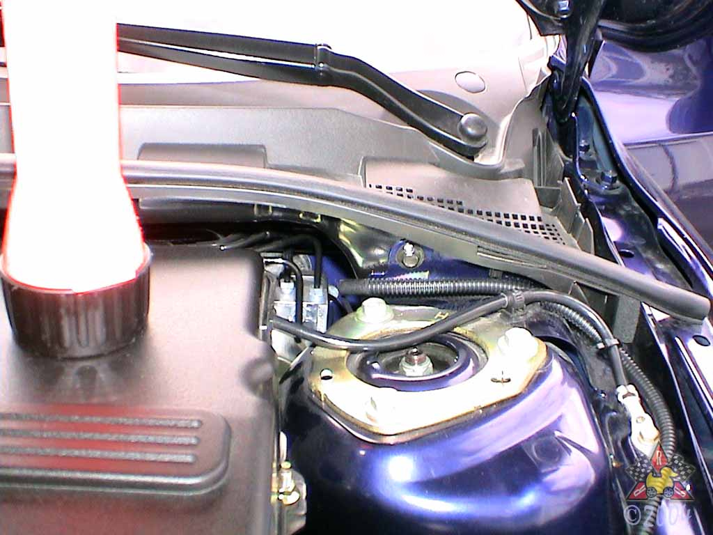
Route the wire along the left fender near the fuse box, securing it
with a zip tie to the large black ground cable near the upper
strut mounting bolts.
|
|
|
|
Replace Trim Panel
|
|
|
|
|
|
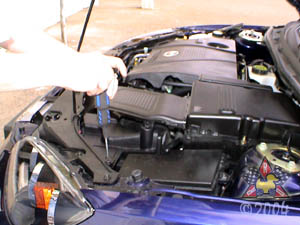
Replace the trim panel you removed earlier. Snap the base of the fastener
into the hole and then screw in the center section.
|
|
|
|
Disengage Hood Latch Cable
|
|
|
|
|
|
Remove the cable from the latch, and be careful that the hood doesn't close!
|
|
|
|
Secure Hood Latch In Unlocked Position
|
|
|
|
|
|
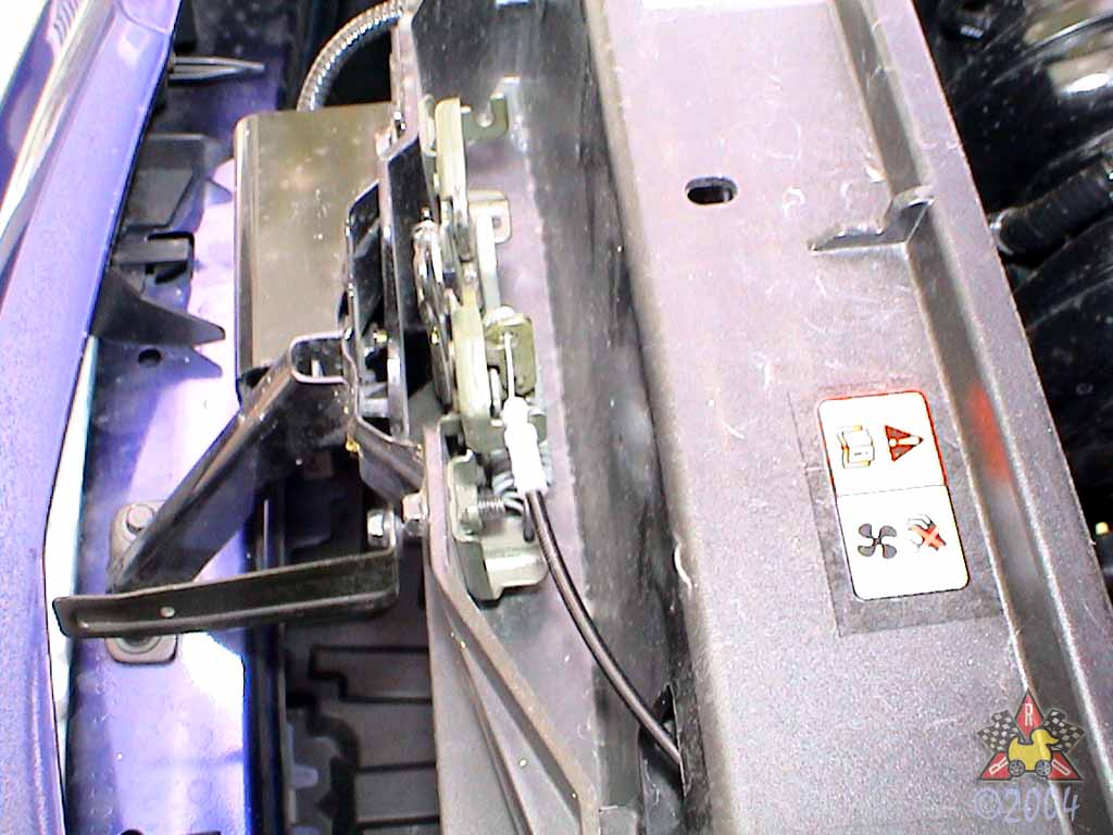
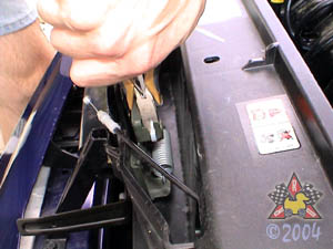
Just to be sure that the hood can't be locked while you have the
cable disconnected, move the latch to the unlocked (release) position
and zip-tie it there. If the hood closes while you have the cable
removed, that would be bad. Very bad.
|
|
|
|
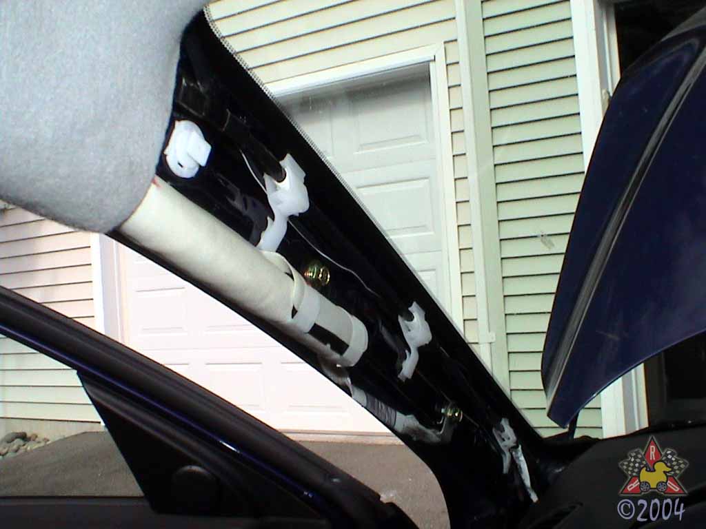
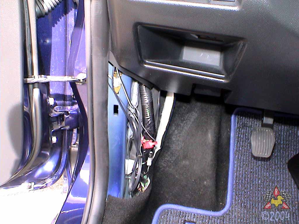
Remove Hood Latch Cable From Clips
|
|
|
|
|
|
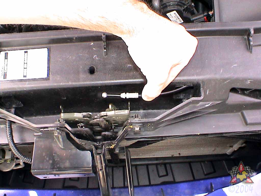
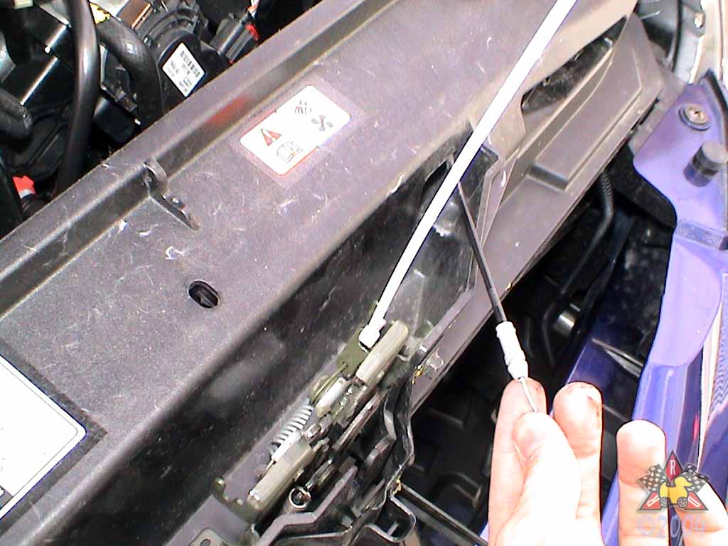
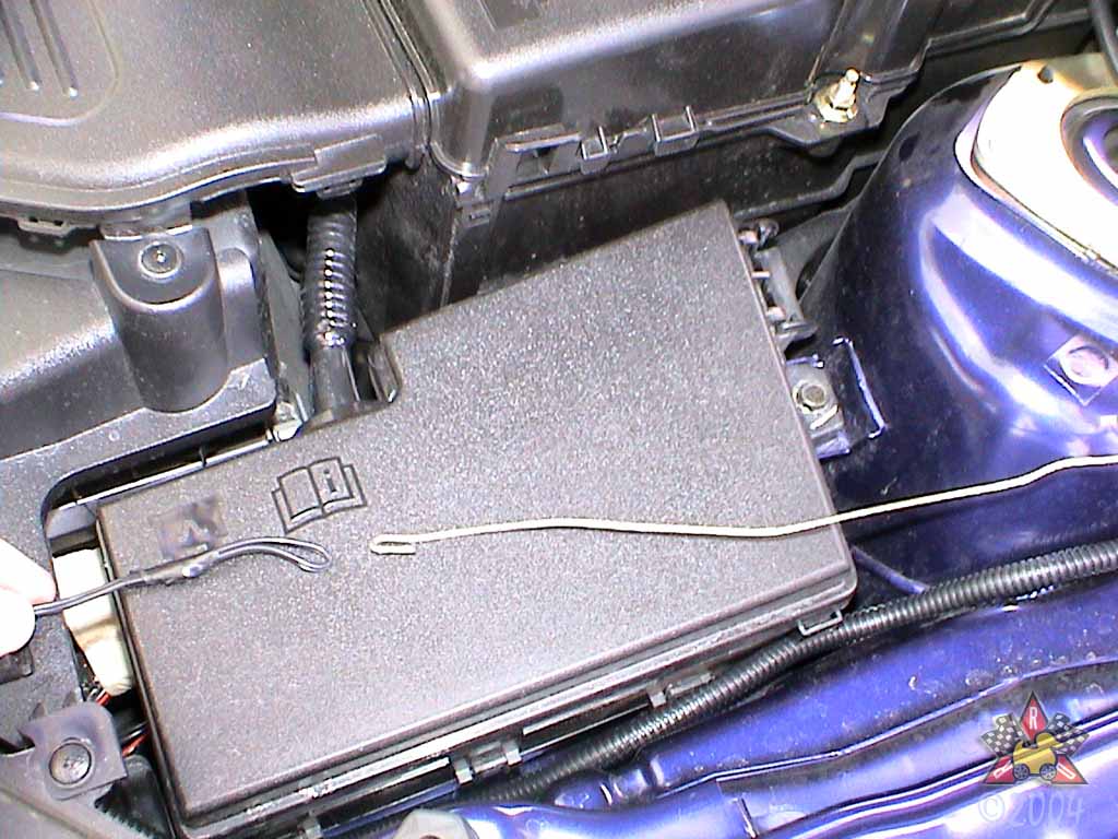
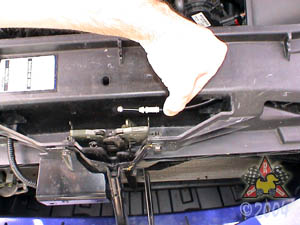
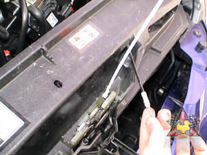
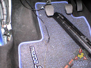
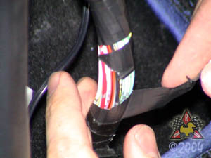
There are several little clips that hold the hood cable; one is near where the
stripe on the cable in the picture is. You'll need to allow some
slack in the cable for future steps, so remove the cable
from the clips. It just slides out.
|
|
|
|
Pull Hood Release Cable Into Interior
|
|
|
|
|
|
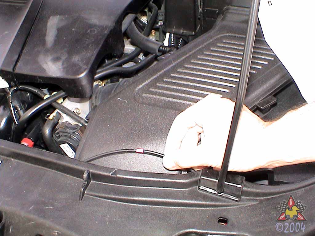
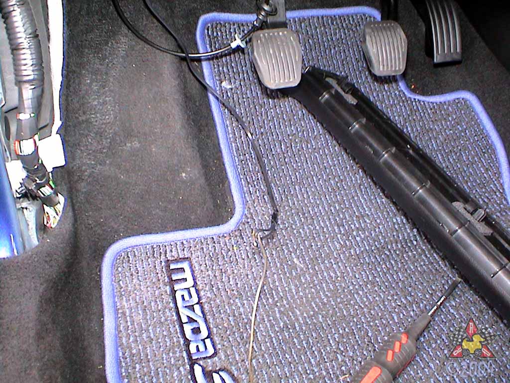
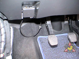
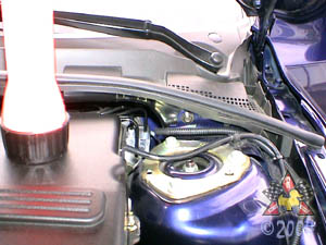
Follow the cable from the lever up to the firewall and
loosen it from the rubber grommet up there. Wiggle it around
and it should come free pretty easily. Pull the grommet out, too.
|
|
|
|
Attach Sensor Wires to Fish Tape
|
|
|
|
|
|
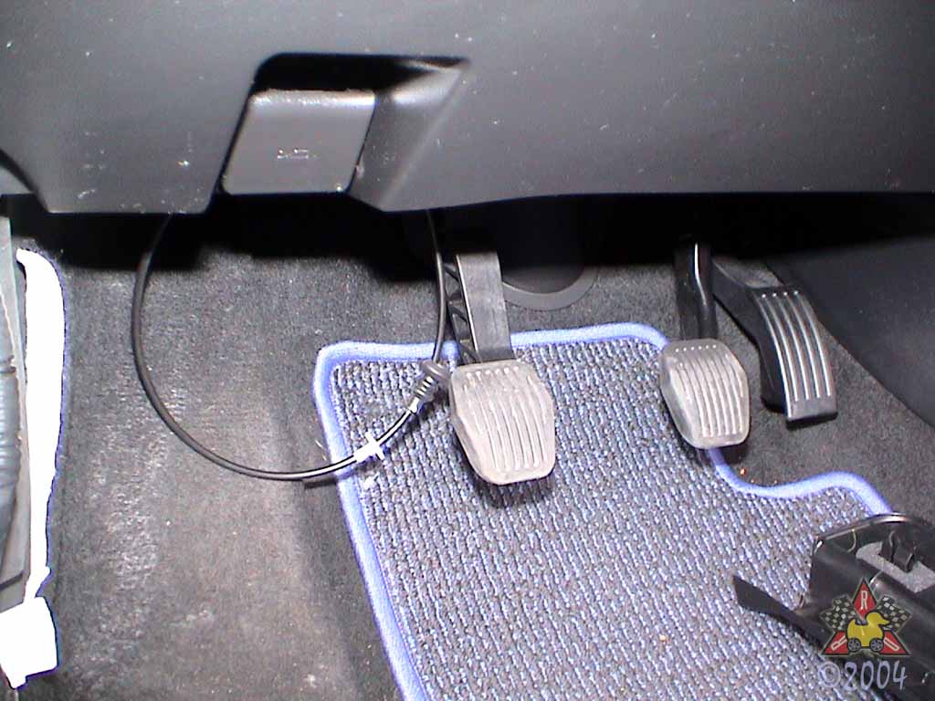
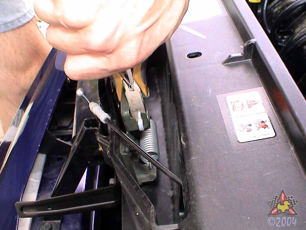
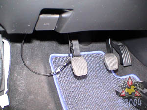
If you don't have a fish wire or special tool, a metal coat hanger
or a piece of stiff wire will do. Make a loop in the end of the
temperature sensor wires and secure it with electrical wire. Then
thread the fish wire (or coat hanger with a hook on the end) through the
firewall gromet for the hood release cable, starting from the interior
of the car. Then hook the wire loop around the hook in the fish wire
and pull the wires back into the interior of the car.
|
|
|
|
Pull Most of Sensor Wire Slack Into Interior
|
|
|
|
|
|
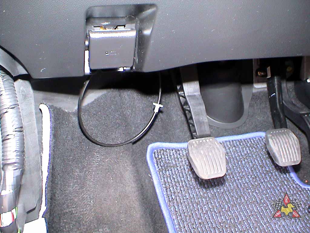
Now that you have the sensor wiring through the firewall,
pull almost all of the slack into the interior and secure
the wire loom to its final position in the engine bay.
|
|
|
|
Reattach Hood Release Cable
|
|
|
|
|
|
Cut the zip tie you put on the hood latch and reattach the cable.
Test that the latch/cable works before you shut the hood! After running the
wires for the temperature sensor through the grommet, shove the gromet and retainer
back up against the firewall where they were originally.
|
|
|
|
Attach Temperature Sensor Wires To Harness
|
|
|
|
|
|
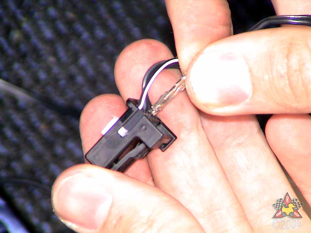
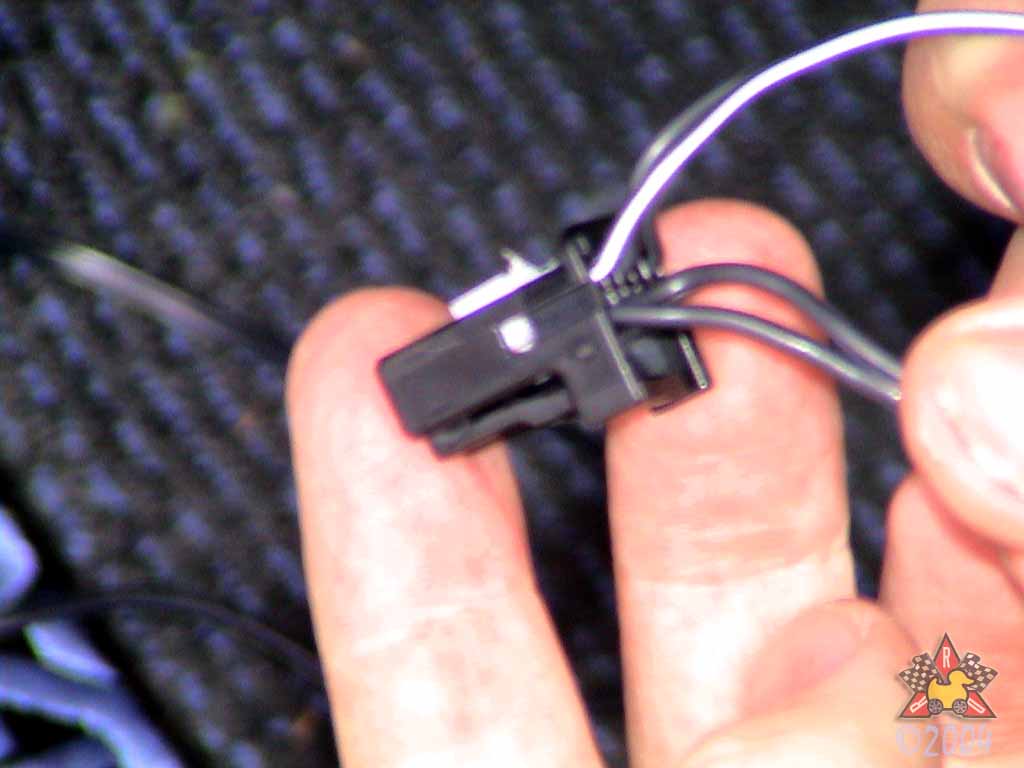
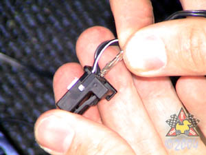
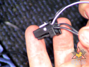
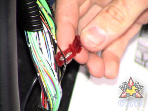
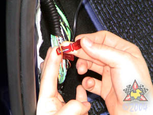
Slightly lift up the white locking tab in the harness so you can
add in the new wires. Attach the temperature sensor wires that you just pulled
through the firewall to the temperature sensor harness
in the positions shown in the instructions. As the
harness is shown in the picture, they go in the
lower left two holes. Polarity doesn't matter. Press the white
locking tab on the harness back down to lock the wires in.
|
|
|
|
Unwrap Wiring Bundle
|
|
|
|
|
|
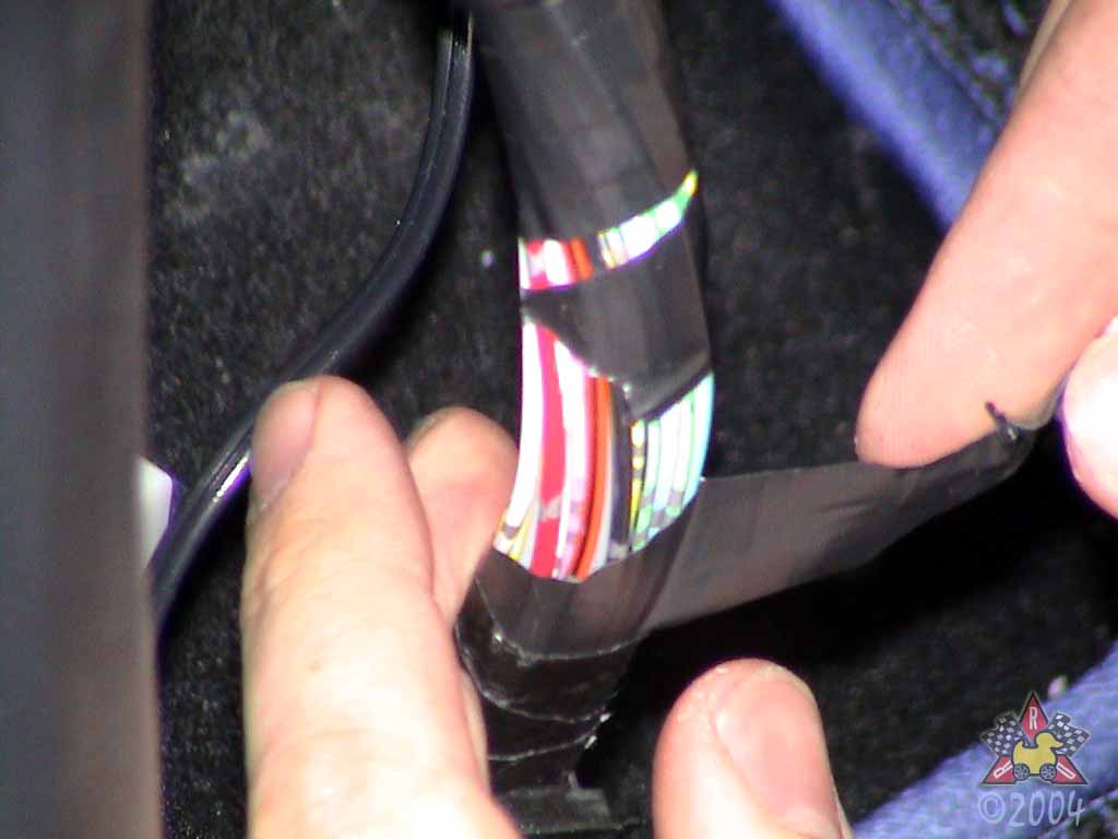
There is a large wiring bundle behind the driver's side
kick panel, and you need to access two of these wires.
Cut and unwrap the electrical tape in a convenient place
to gain access to the wires.
|
|
|
|
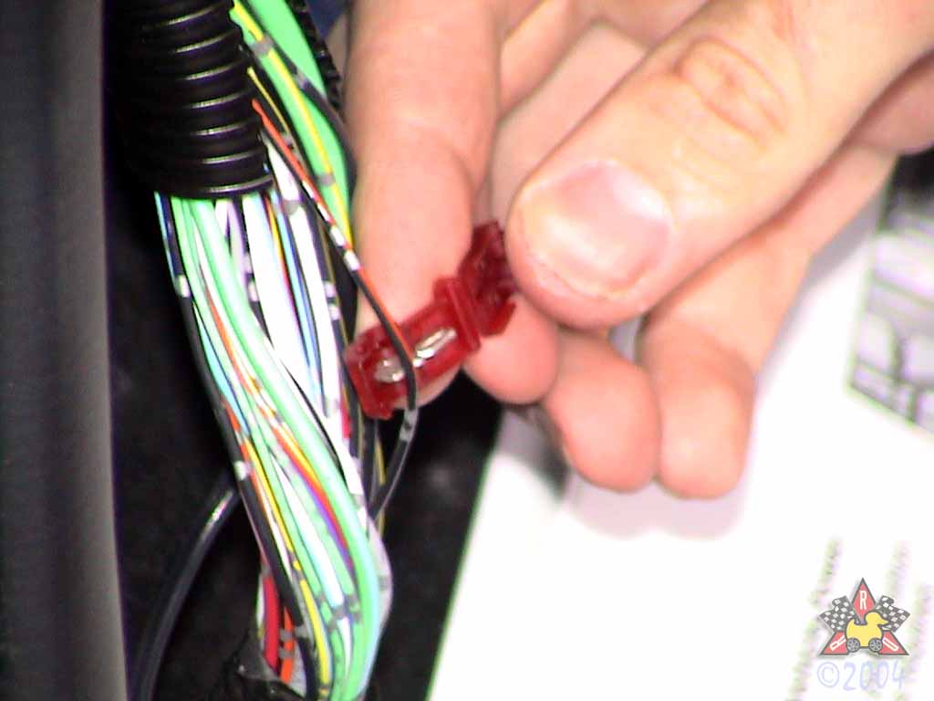
Locate Orange Wire with Black Stripe
|
|
|
|
|
|
Note!! If your instructions say to use the black wire with
the orange stripe, DO NOT LISTEN TO THEM. There is a type in the instructions,
and I confirmed this by contacting Homelink directly. If you use the black/orange
wire instead of the orange/black wire, your Homelink buttons will not work. I have
reported this to Mazdastuff.com, and they said they would make sure that
future instructions shipped with these mirrors had the correct wire listed.
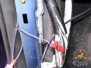
Locate the Orange wire with the Black Stripe and attach
one of the provided T-taps to the wire. Just place the wire in the
groove in the metal part, close the plastic part over it, and press.
Sometimes I'll use a pair of pliers to make it easier to pinch the
halves of the plastic part together.
|
|
|
|
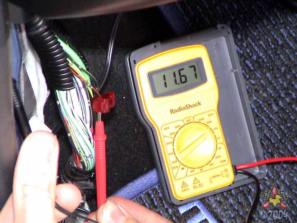
Check For Voltage [optional]
|
|
|

|
|
|
The Orange/Black wire should be constant battery voltage (about 12V),
so if you have a multimeter handy, go ahead and check the voltage.
|
|
|
|
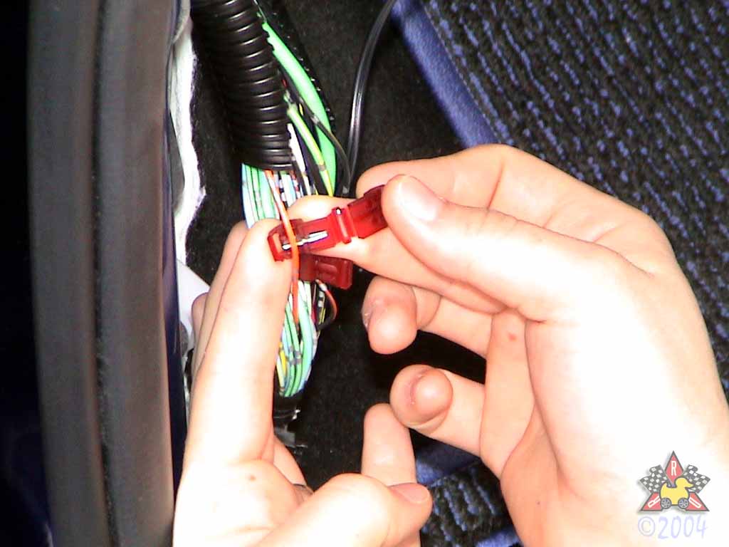
Locate Orange Wire With Yellow Stripe
|
|
|
|
|
|
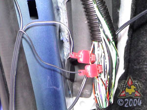
Attach the other T-tap to this wire just like you did
for the other one. This is an ignition circuit wire, so there
should be 12V at this wire when the key is in the "ON" position
and it should be 0V when the key is in the "ACC" or "OFF" positions.
|
|
|
|
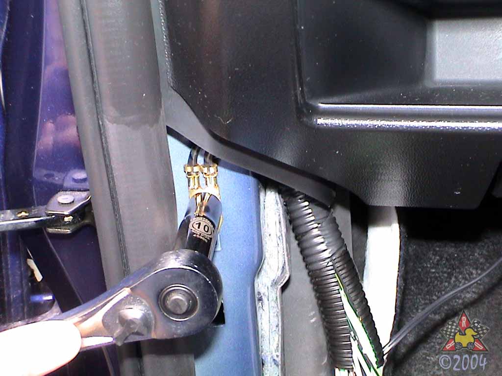
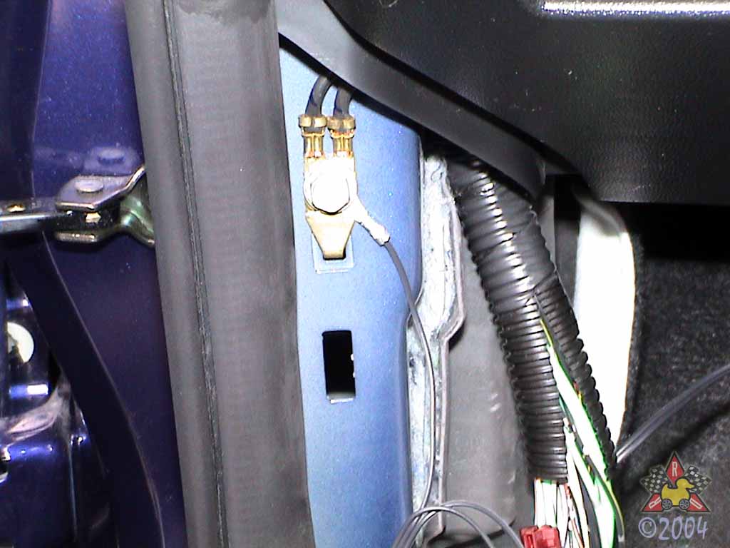
Attach Grounding Ring to Grounding Screw
|
|
|
|
|
|
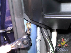
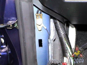
One of the wires on the harness for the mirror has a ring terminal
on it. This is the ground wire, and it needs to be attached
to a secure chassis ground. Luckily, there just happens to
be a grounding screw right in the general area you're already in.
Unscrew the 10mm bolt and attach the ring terminal.
|
|
|
|
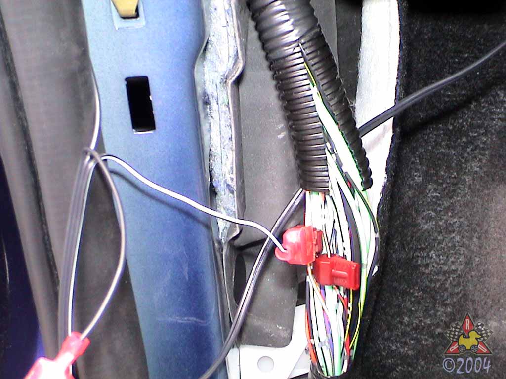
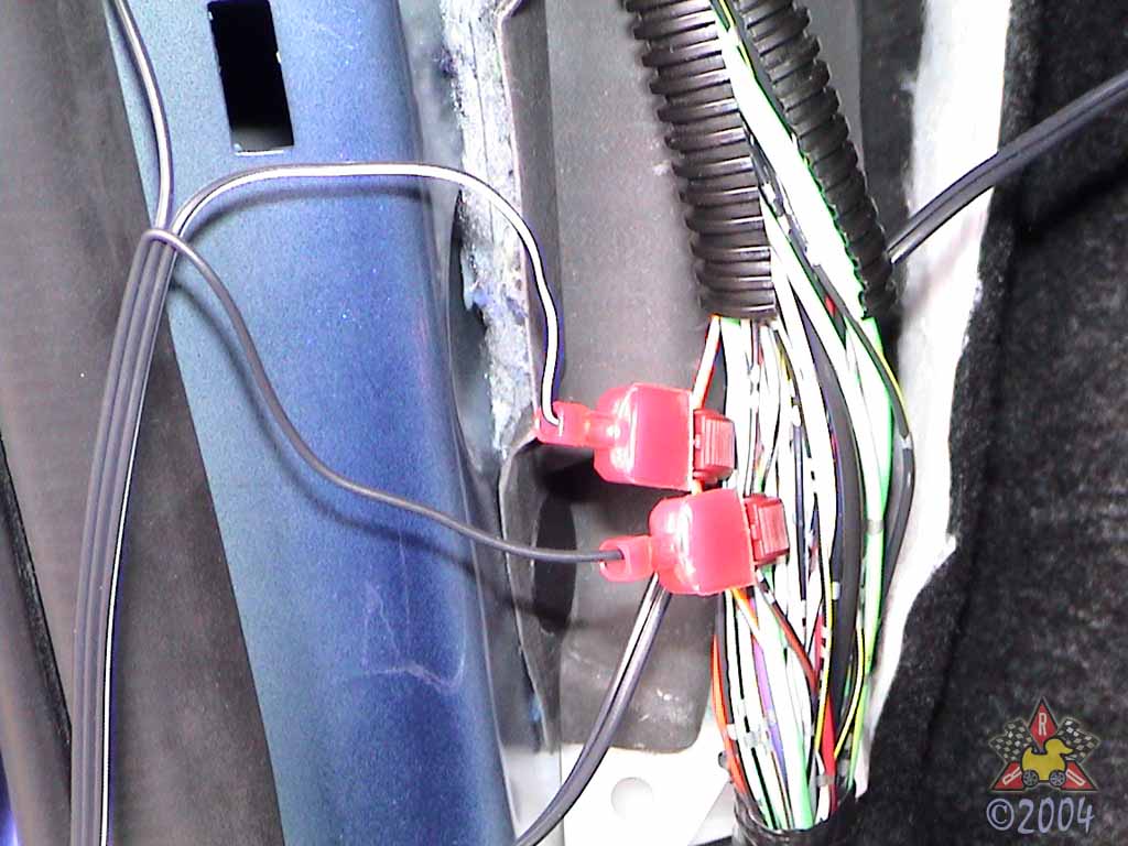
Attach Harness Power Wires
|
|
|
|
|
|
The Black wire with the White Stripe on the mirror harness
should be connected to the Orange wire with the Yellow Stripe
in the factory bundle. The Black wire (no stripe) on the
mirror harness should be connected to the Orange wire
with the Black Stripe in the factory bundle.
|
|
|
|
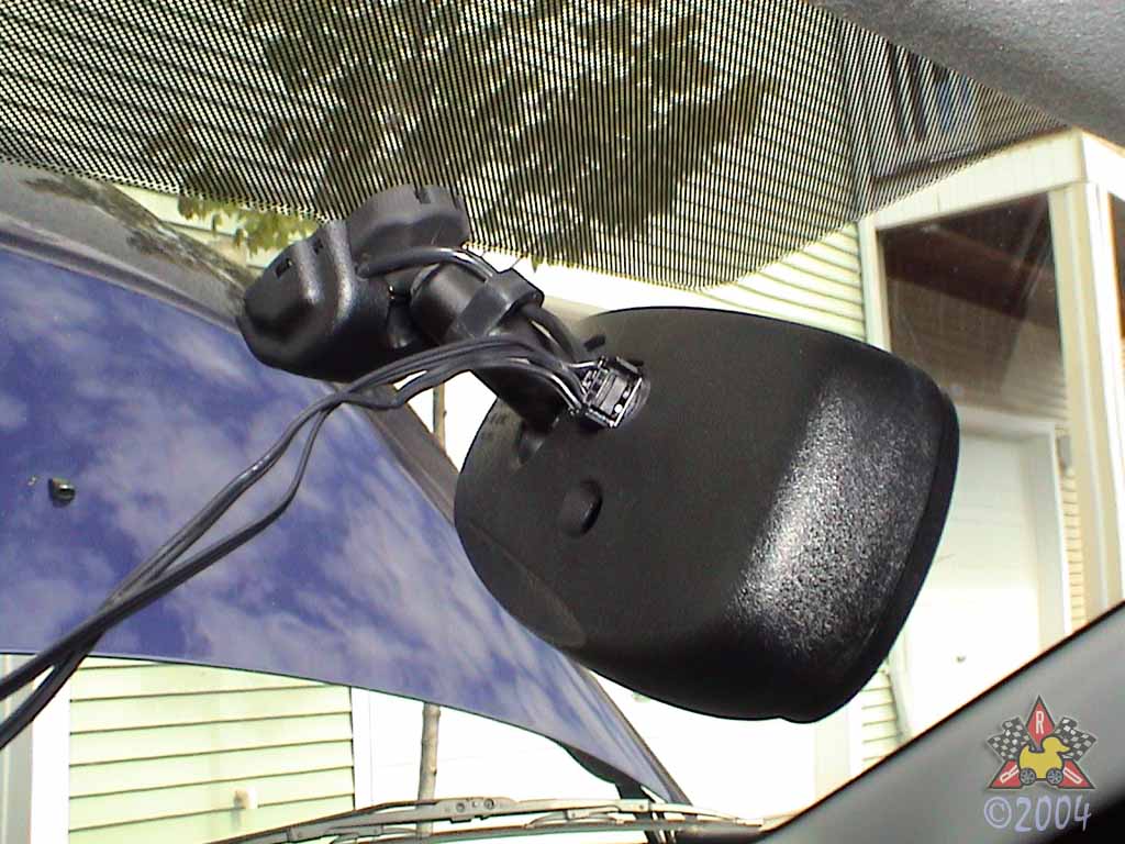
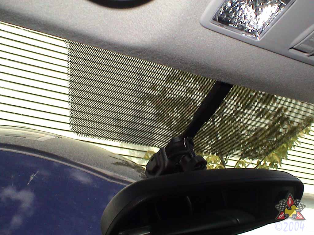
Attach Harness To Mirror
|
|
|
|
|
|
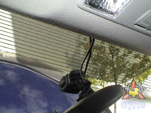
It should just snap right in to the hole in the rear of the mirror.
Stuff the wires up under the headliner above the mirror.
|
|
|
|
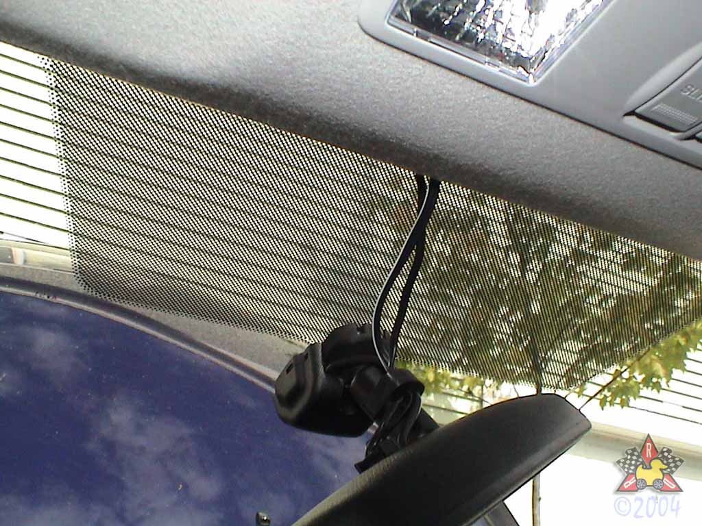
Route And Cover Wires, Part I
|
|
|
|
|
|
Gently pull down on the headliner and stuff the wires
up under it. Also attach the plastic trim piece to the
mirror mount and make sure its prongs extend up under
the headliner.
|
|
|
|
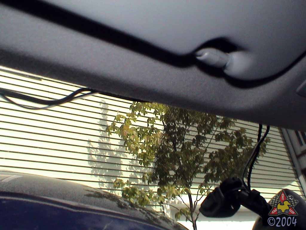
Route Wires, Part II
|
|
|
|
|
|
Route the wires down the A-pillar, making sure you don't get in
the way of the side air curtains if you have them. Secure
the wires with the provided zip ties. Extend the wires down along
the side of the dash, in the area that will be under the
weatherstripping when it is reattached.
|
|
|
|
Replace Weatherstripping and Secure Wires
|
|
|
|
|
|
Just push the weatherstripping back into place. Secure
the new wires in place with the provided zip ties.
|
|
|
|
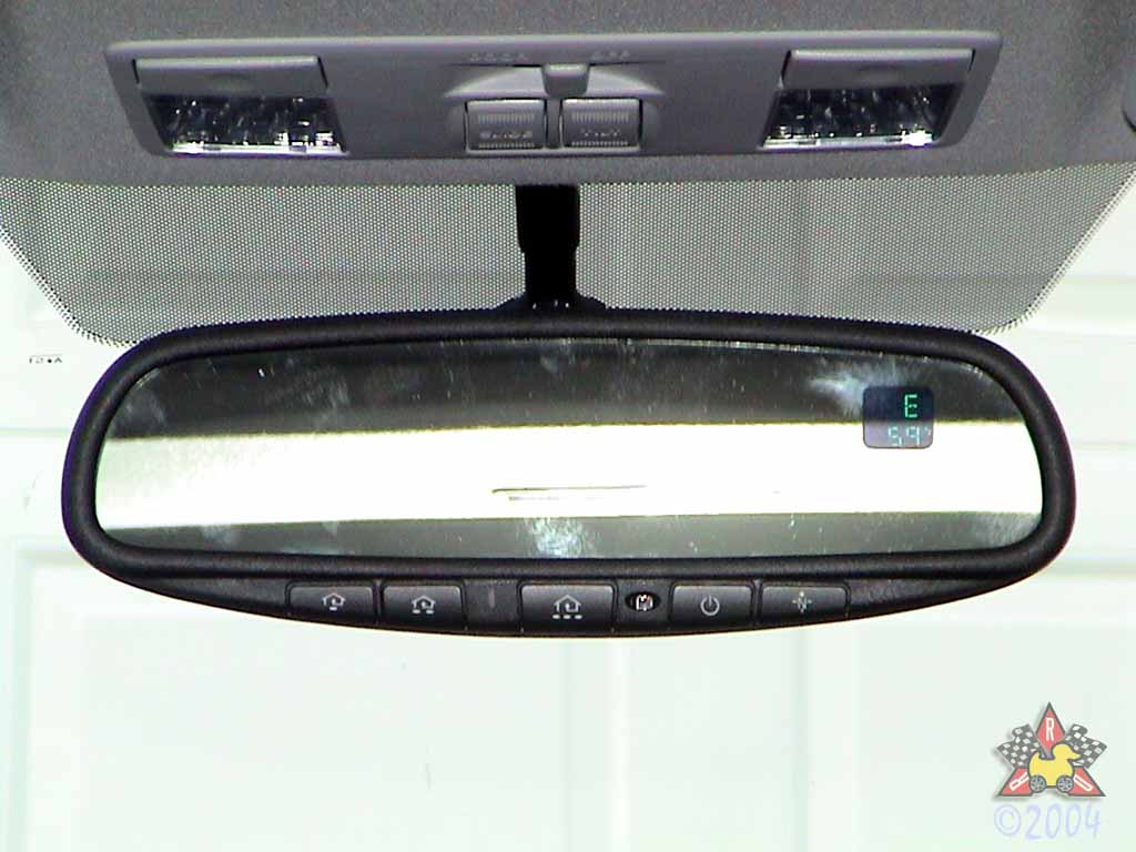
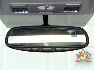
Test Mirror Function
|
|
|
|
|
|
Reconnect the negative terminal of the battery. Turn the ignition switch to "ON".
Make sure that the green LED to the left of the center switch is on. If it's not on,
push the mirror's power button to make it so. In a well-lit area, place your hand over the
photo sensor on the front of the mirror. Within a few seconds, the mirror should darken.
Remove your hand from in front of the photo sensor, and the mirror should clear within
a few seconds. Now press any of the homelink buttons and make sure that a red LED
lights up in the same location as the green LED. If you're in really bright light, you
may need to turn the green LED off (by pushing the mirror's power button) in order to
see the red LED. Finally, you'll need to drive your car in a circle a couple times very
slowly (under 5mph) to calibrate the compass. See the mirror's directions for getting
the correct magnetic zone if you like.
|
|
|
|
Replace Kick Panel and Scuff Plate
|
|
|
Put them back on in the reverse of how you took them off.
the new wires in place with the provided zip ties.
|
|
|
|
Set Up Homelink Functions
|
|
|
You can get the instructions on the
Homelink Website, and they're
slightly different for different manufacturers of garage door openers
and home automation equipment.
|
|