|
Jack Up Car and Support Front End
|
|
|
If you have active aero, you'll need to remove the center jacking point
cover first. Then support the car on
jackstands, making sure that the support point on one side
doesn't interfere with being able to unbolt the lower control arm on
that side (I picked the driver's side). As always, check to be
absolutely sure that the car is supported securely and that it is not at
all unstable while supported by the jack stands. If it falls, it will
squish you and you will probably not live to tell the tale. Chock
the rear wheels, too.
|
|
|
|
Remove Front Undercovers (or Active Aero)
|
|
|
|
|
|
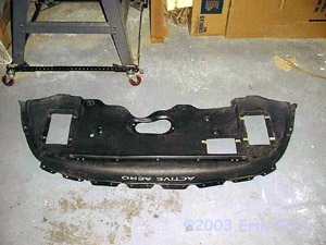
Remove the plastic tray(s) that cover the front underside of the engine
bay. These are held on by 10mm and 12mm bolts, all of which are
easily accessible. If you have active aero, you need only remove
the outer 4 (2 on each side) 12mm bolts on the central metal support bar
to remove the plastic aero dam.
Detailed Active Aero removal instructions can be found
here.
|
|
|
|
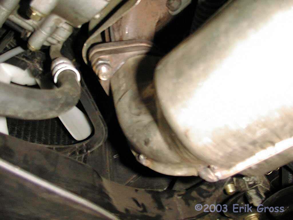
Remove Downpipe
|
|
|
|
|
|
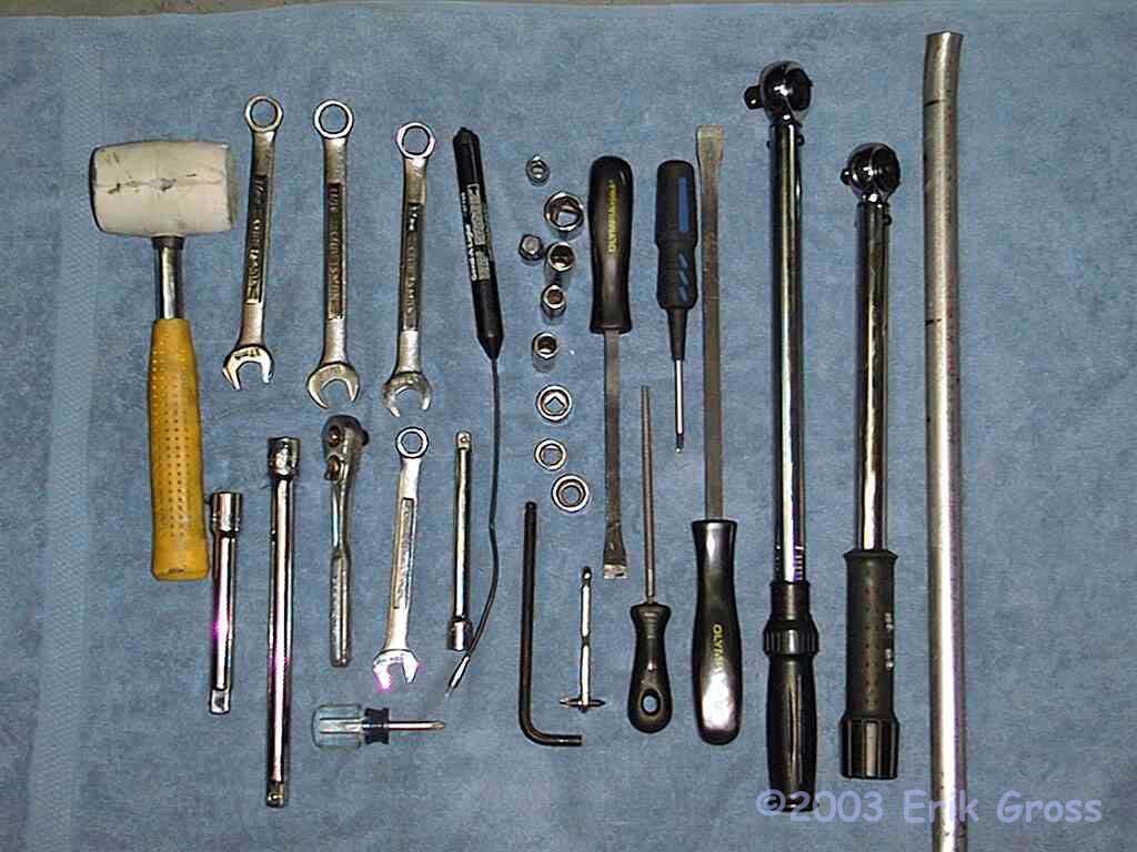
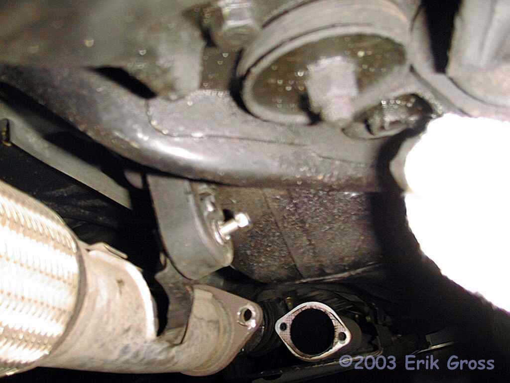
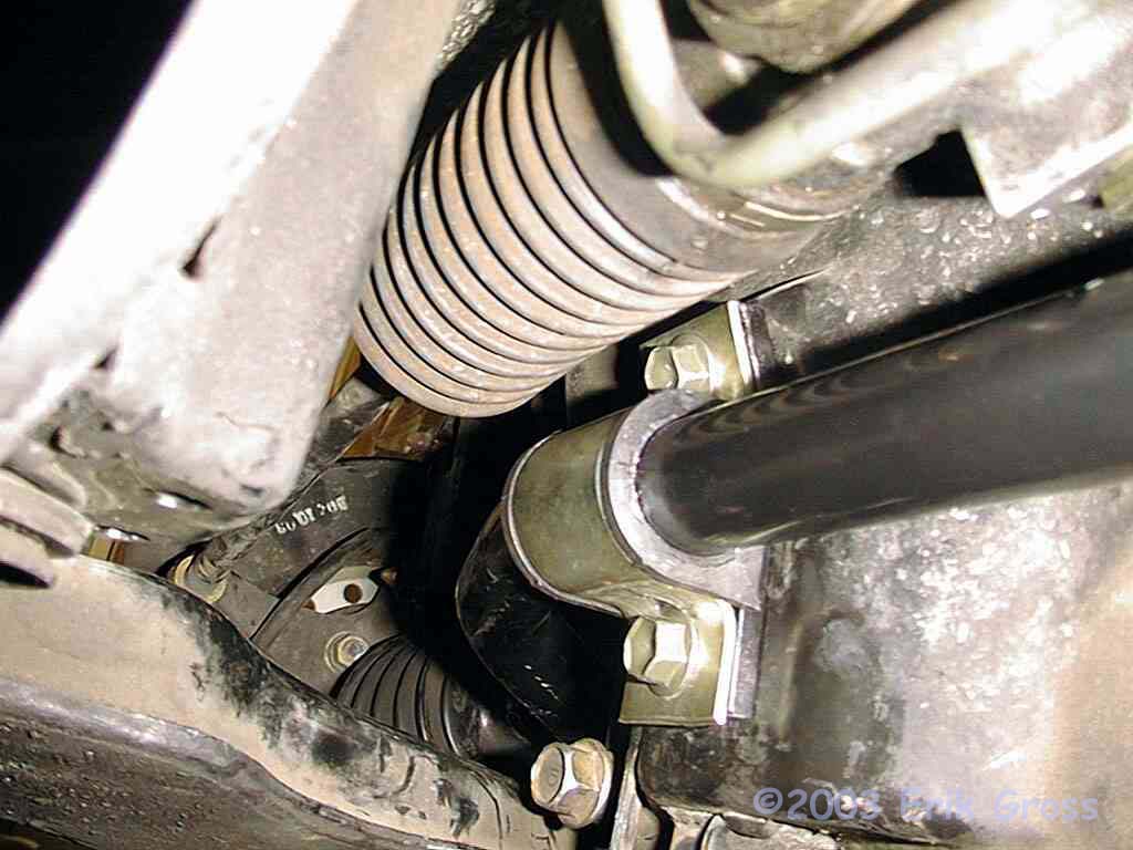
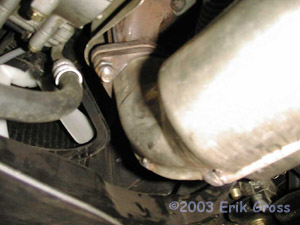
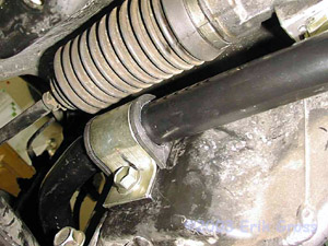
You did remember to soak those nuts and bolts with penetrating oil last
night, didn't you? If not, all is not lost - just make sure you
let them soak for at least 15 minutes. There are two 19mm nuts
(36ft*lbs) on
the flanges for the front and rear oxygen sensor housings and the bolts
that connect the downpipe to the catalytic converter are 17mm (36
ft*lbs).
They may take upwards of 100ft*lbs to break loose if you've never
removed them. Use the cheater bar if you need to. There
is one exhaust hanger for the downpipe and that bolt is a 12mm bolt (9
ft* lbs) and
should come off easily.
|
|
|
|
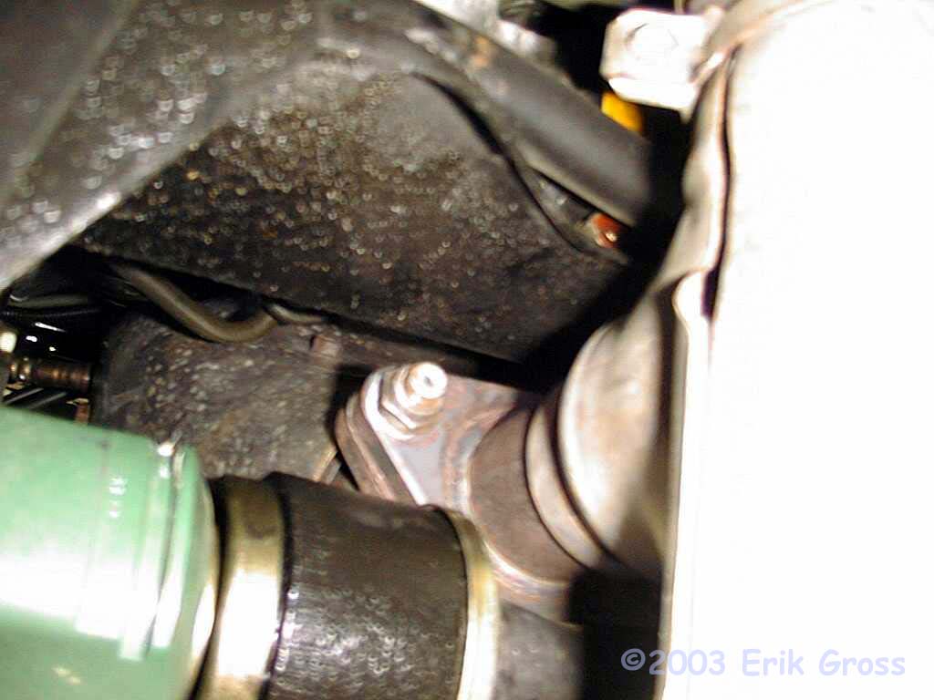
Remove Right and Left Frame Members
|
|
|
|
|
|
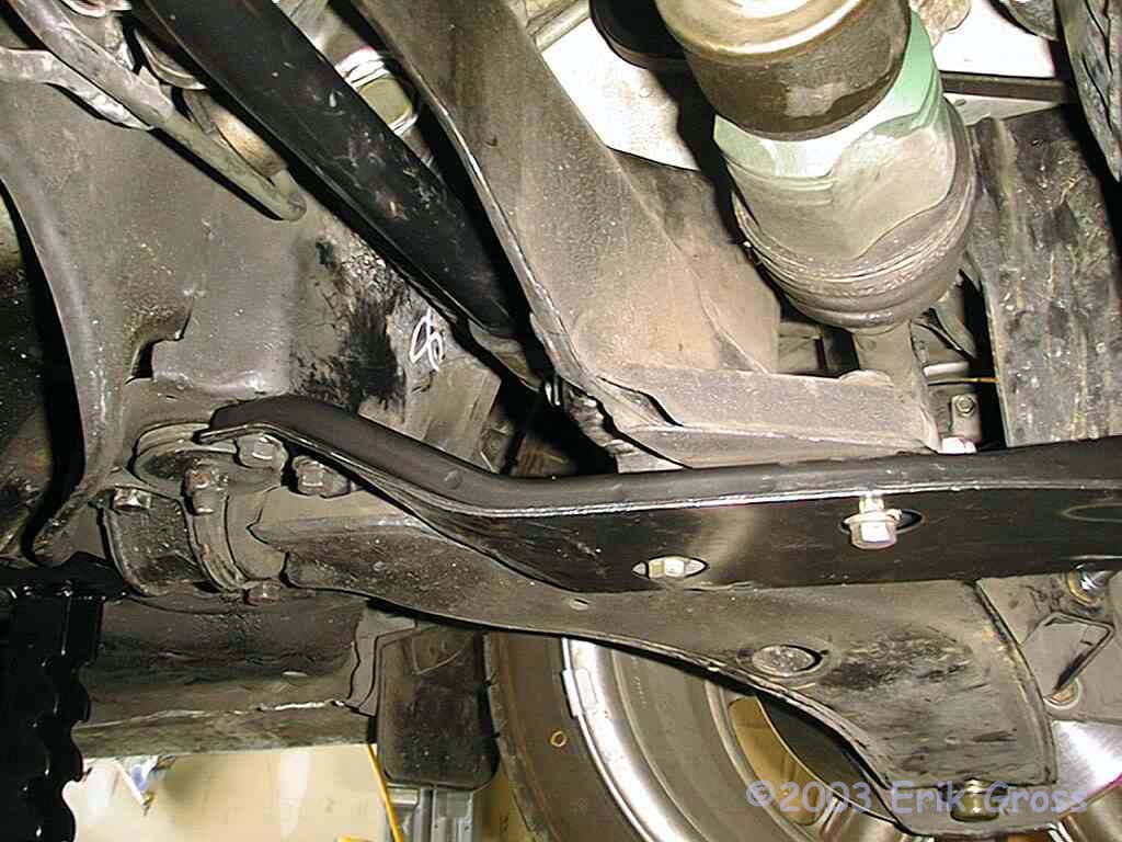
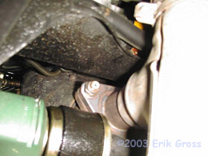
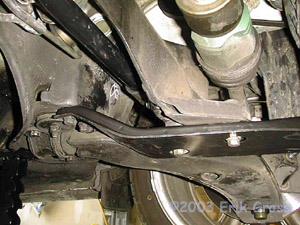
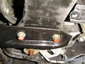
You'll need to remove the left and right frame members to give
yourself room to access the anti-sway bar bushing brackets. There
are numerous 14mm bolts (43-51 ft*lbs) (left member pictured) that are
basically all in plain sight. There are also two 12mm bolts that
attach the clutch vacuum assist tank (double round tube shaped thingy
near front passenger side) to the right member. You'll need to
remove those two bolts, too, but you don't have to remove the clutch
vacuum assist reservoir. And one more thing... there are two plastic fasteners
that attach the left member to the cover for the left side of the
engine. Use your stubby screwdriver to "unscrew" them
and then pull them out.
|
|
|
|
Support Driveshaft
|
|
|

|
|
|
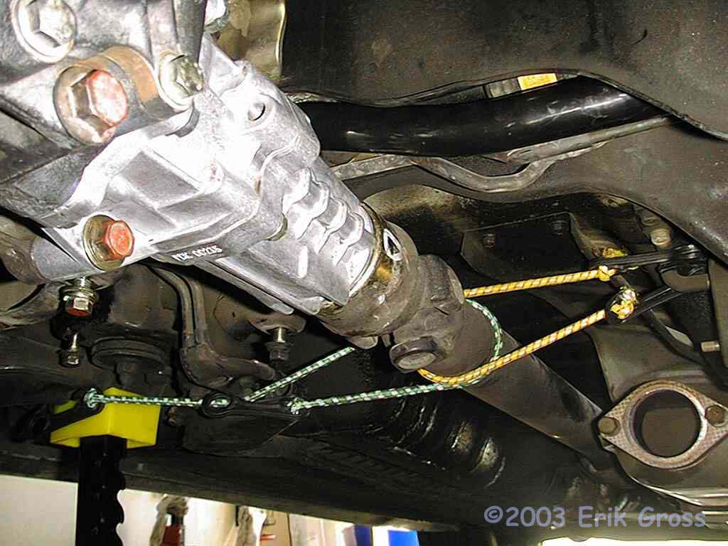
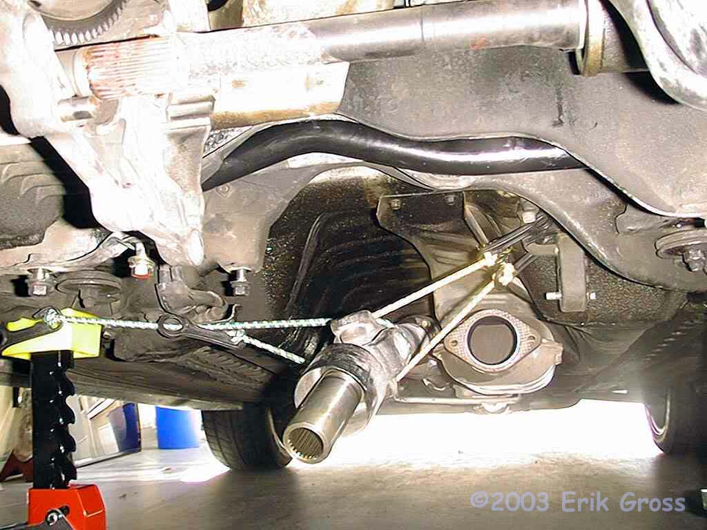
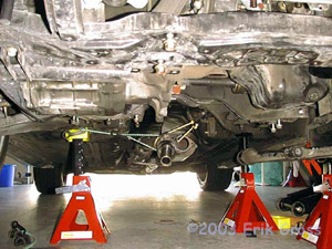
Since you'll be removing the transfer case, you need to support the front end of the driveshaft
so as not to put unnecessary stress on the universal joint. You
can use string, rope, a jackstand, or anything else that's safe, so long
as the driveshaft is supported. I used two bungee cords as shown
in the picture and attached them to various non-moving parts under the
car. This worked great for me.
|
|
|
|
Drain Transfer Case Fluid
|
|
|
|
|
|
You need to drain the transfer case fluid before you remove the transfer
case, lest you let transfer fluid leak all over your floor from the output
shaft housing. This is a 17mm drainplug (22 ft* lbs) and you MUST use
a new crush washer (gasket) when reinstalling it.
|
|
|
|
Remove Transfer Case
|
|
|

|
|
|
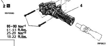
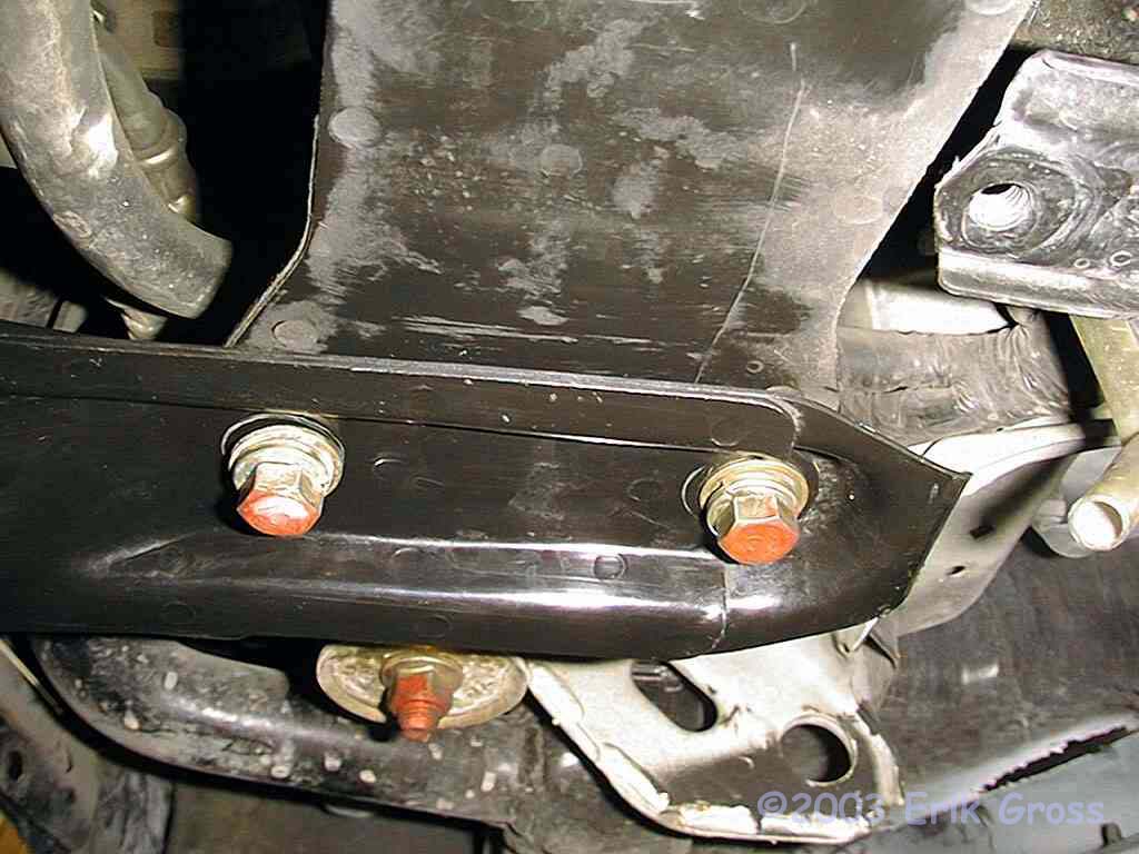
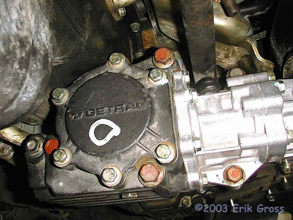
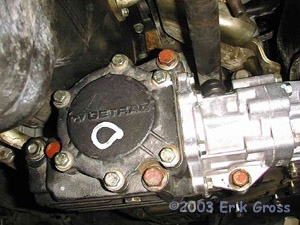
There are five 17mm ('91-'93: 61-65ft*lbs '94+: 18-22ft*lbs) bolts
that attach the transfer case to the transaxle. You can see four of
them with their red heads in the picture. The fifth one is above and
to the right of the rightmost red one. Once you remove these bolts,
insert a large screwdriver or prybar between the transfer case and the
transaxle. Gently pry the transfer case toward the driver's
side. Once you break it loose, it should slide off the transaxle
output shaft with little resistance. Remove the front end first,
rotate the front downward, and then slide the transfer case off of the rear
driveshaft. Be careful not to drop the transfer case on your head
:-) It's heavier than I first thought. Also, there will be some
oil left in the splines of the rear driveshaft, so put a paper towel or rag
under there to catch the oil.
|
|
|
|
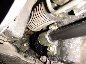
Unbolt Stock Anti-Sway Bar Endlinks
|
|
|
Using a 14mm wrench or socket on the nut and a 14mm open-end wrench to
hold the other end, unbolt the end links from the stock anti-sway
bar. Should be very easy.
|
|
|
|
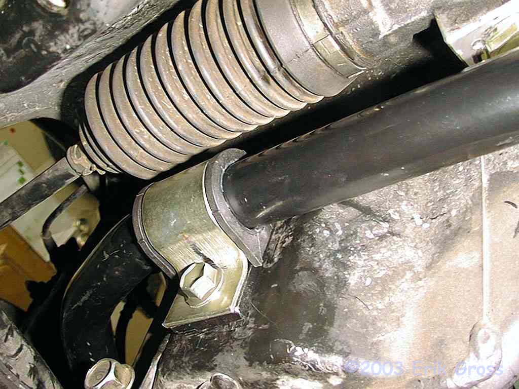
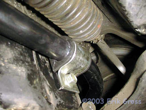
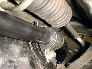
Unbolt Stock Anti-Sway Bar Bushing Brackets
|
|
|
Using a 14mm socket, unbolt the brackets that fasten the stock anti-sway
bar to the rear crossmember. There are two 14mm bolts (29ft*lbs)
on each bracket. This, also, should be very
easy. At this point, the stock anti-sway bar is completely detached
from the car.
|
|
|
|
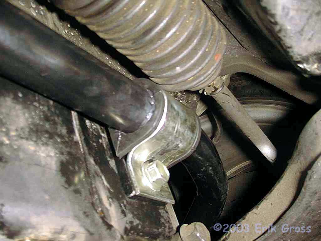
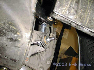
Unbolt Control Arm
|
|
|
|
|
|
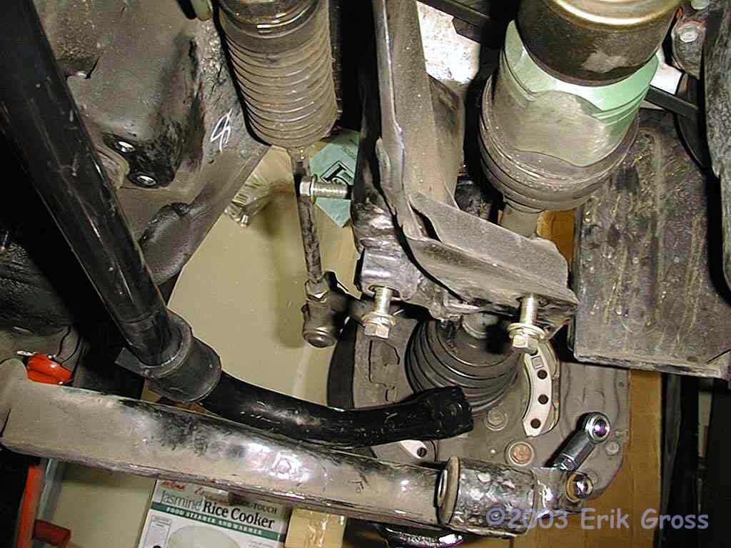
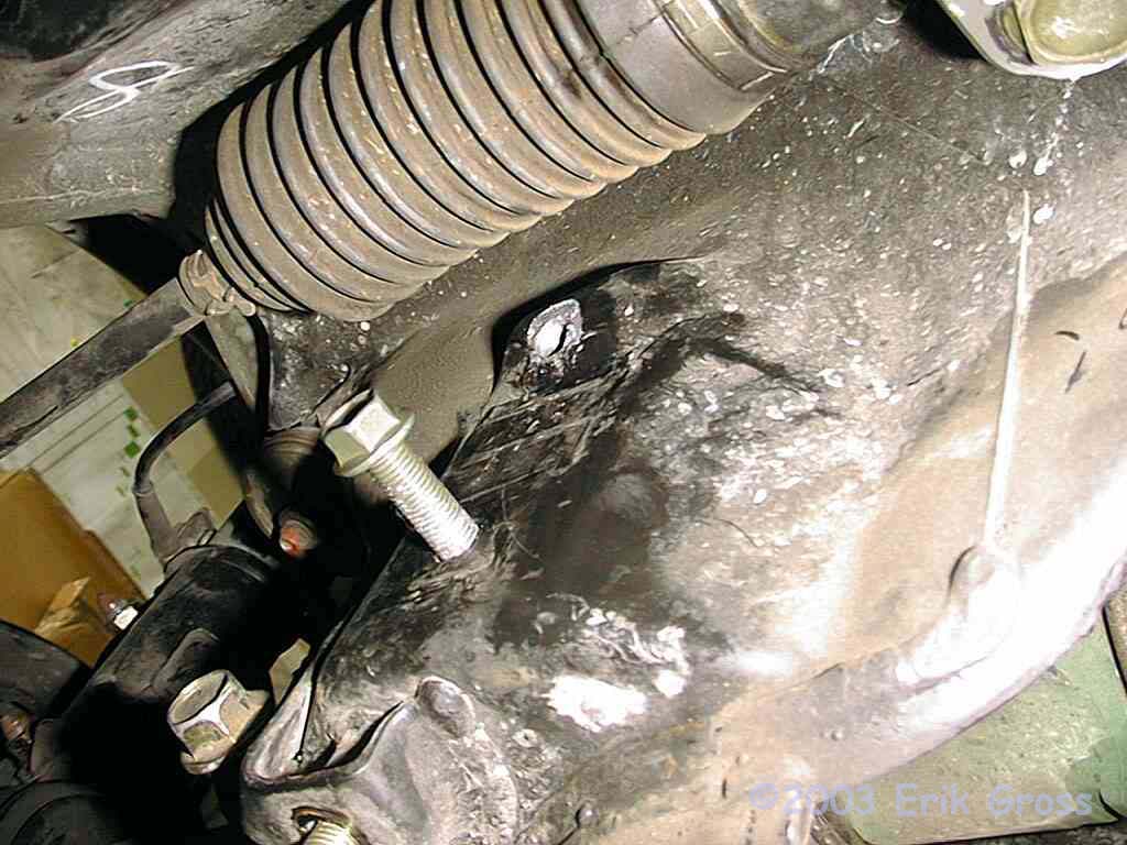
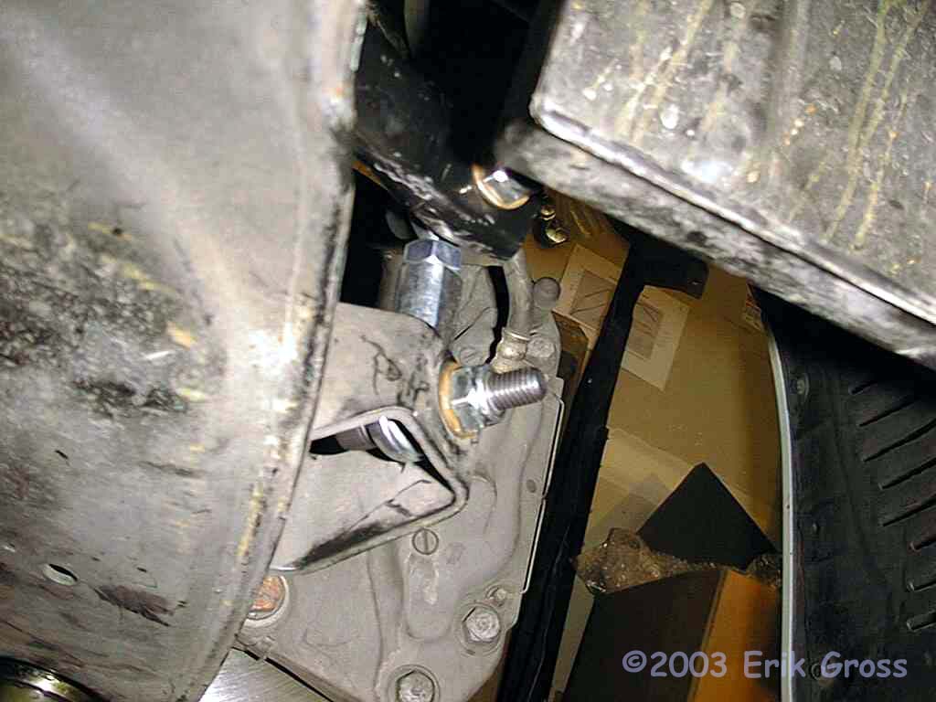
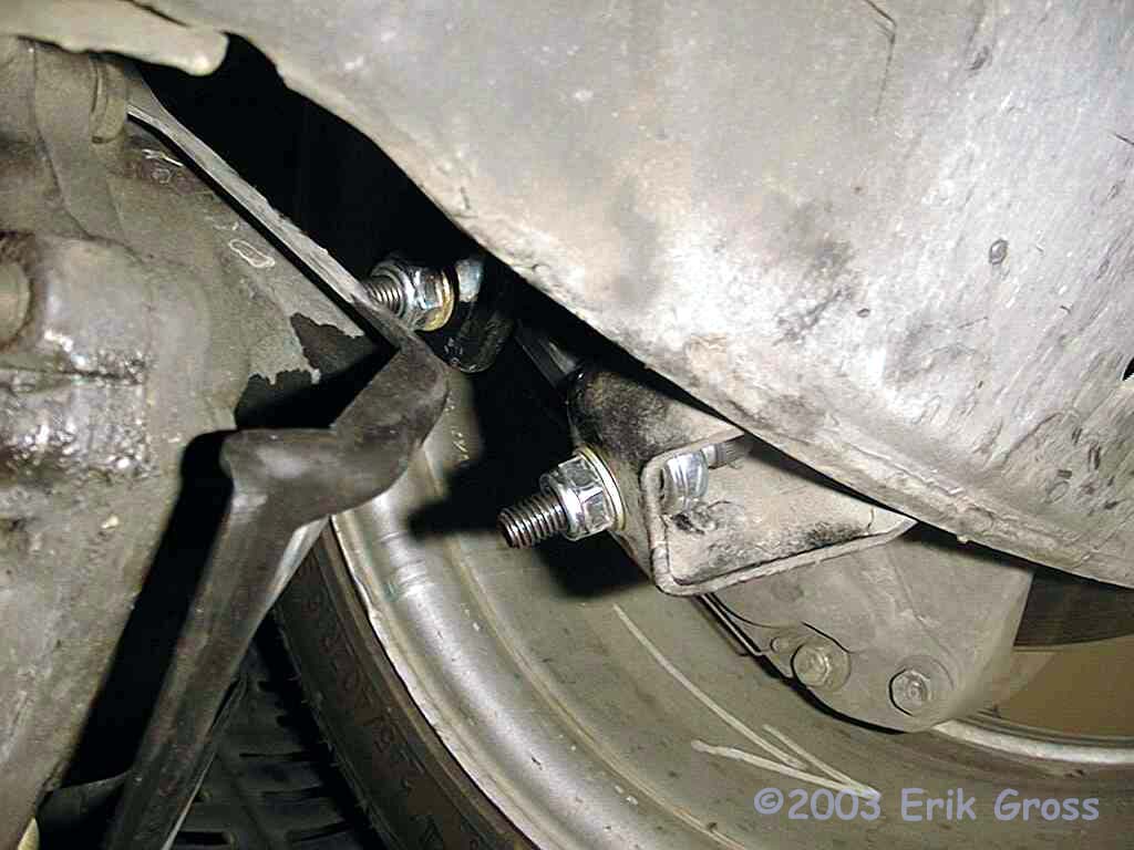
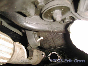
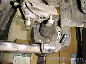
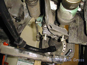
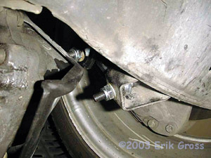
In order to get clearance to get the new anti-sway bar in position, you'll need to unbolt the
inboard side of the lower control arm on one side. I picked the
driver's side, and you don't need to remove the wheel as I did. The front
of the lower control arm is anchored by a 17mm bolt/nut (78
ft*lbs) that extends through the bushing in the lower middle of the
second picture. You'll need to get a wrench on the head of the
bolt to stabilize it and then crank away on the nut to get it off.
The rear of the control arm is anchored by two 17mm bolts (72-87
ft*lbs for the big one and 65ft*lbs for the smaller one) and two 14mm
nuts (29ft*lbs). The manual says that the two 14mm nuts are not
reusable, but since they have a lock washer, you can probably get away
with just using some Lock-Tite in a pinch. Once the control arm is
unbolted, it will rotate downward, and you need to put something under
it to support it so that you don't stress the ball joint. I used a
jackstand as you can see in both pictures.
Re-assembly Note: The service manual indicates that the 17mm through bolt/nut that anchors the front
of the control arm must be only temporarily tightened when the car is
suspended in the air. The final tightening must take place with
the car "on the ground in an unladen condition."
Installation Note: Some would consider this step optional. In fact,
the service manual indicates that the removal of the control arm is not
necessary to replace the stock anti-sway bar. I fought with this
@#$% thing for at least 4 hours trying to maneuver the stock bar every
which way I could in an attempt to get it off. I eventually did
find a way to get it off without unbolting the control arm, but in
retrospect, it's not the safest thing to do and I'm not even going to
describe it because I'm convinced that there is no way the bigger,
bulkier Saner bar will fit back in without unbolting the lower control
arm. It's not that hard to complete this step; get over it and
just unbolt the @#$% thing and you'll be much less frustrated.
|
|
|
|
Remove Stock Anti-Sway Bar
|
|
|
With the control arm unbolted, this should be extremely easy.
Just rotate it as necessary and pull it out.
|
|
|
|
Lubricate New Polyurethane Anti-Sway Bar Bushings
|
|
|
Saner provides bushing lube - put a light coating on the inner surface of the new bushings.
|
|
|
|
Install Bushings On Saner Anti-Sway Bar
|
|
|
Put the new bushings onto the Saner anti-sway bar; their position doesn't have to be exact
as the lube will allow them to slide along the bar as you get it into
its final position.
|
|
|
|
Maneuver Saner Anti-Sway Bar Into Position and Support It
|
|
|

|
|
|
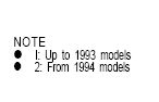
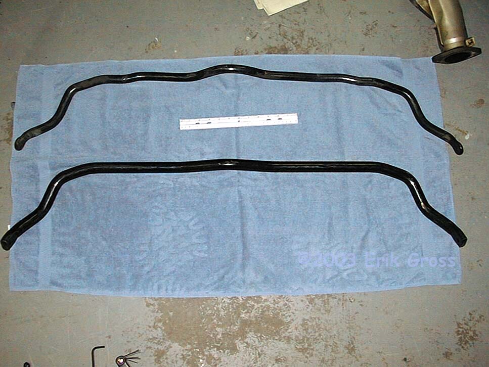
Much the same way as you removed the stock bar, maneuver the Saner bar back into position. Hold it out of the way
in preparation for the next step. I found the most convenient way to support it was to thread the lower
bushing bracket bolt in about 1/2" and then rest the bar on the
bolt.
|
|
|
|
Reattach Inboard Side of Control Arm
|
|
|
Reattach the mounting bolts for the lower control arm. Remember not to fully tighten
the front through-bolt until the car is back on the ground.
|
|
|
|
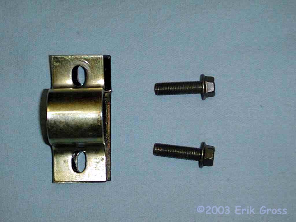
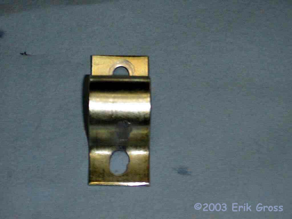
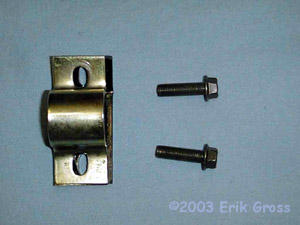
Test-fit Bushing Brackets
|
|
|
Wrap the bushing brackets around the bushings, slip the spacer under the bracket and maneuver
the upper bolts so that you can thread them in 3/8". Once the
upper bolts are threaded in, try to line up the lower bolt holes.
If by some miracle they line up on your car then you can skip the next
couple of steps. If you're like me and everyone else I've talked to,
you get to have some fun now. I found that my brackets needed to
be rotated counter-clockwise to make the lower bolt holes have a prayer
of lining up. That meant that the upper right of the lower bolt
holes needed to be enlarged. Take the bushing brackets off the car
and over to your workbench.
|
|
|
|
Remember Which Way the Brackets Need To Be Enlarged
|
|
|
|
|
|
Stare at the bushing brackets that will make the next 2 hours of your
life a living Hell. Realize you forgot which edge to enlarge. Swear.
Get back under car, groan, and then mount brackets again. Get the bright
idea to mark the edge that needs enlarging with a marking pen before
removing brackets.
|
|
|
|
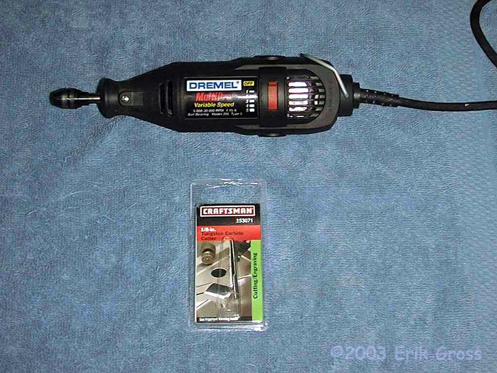
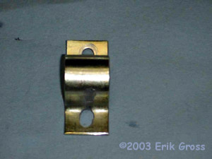
Enlarge Holes With Dremel
|
|
|
The lower hole was enlarged toward the bar and to the
right. The upper hole was enlarged only slightly toward the
bar. The spacer was not modified and the brackets were not
mirror-images (they were identically modified).
|
|
|
|
Cut Groove For Bolt Head With Dremel
|
|
|
This will help keep the bolts from binding so badly when you secure the
brackets.
|
|
|
|
Swear; Remove Metal Splinters
|
|
|
That cutting bit will leave metal splinters everywhere. Some of these are
bound to find their way into your hands. Remove them.
|
|
|
|
Test Fit Bushing Brackets and Spacers Again
|
|
|
Realize that the brackets still don't fit. Get out the thesaurus
to learn some synonyms for the swear-words you've been using.
They're getting old.
|
|
|
|
Repeat Bracket Modification Steps If They Don't Fit
|
|
|
|
|
|
This is what my brackets looked like when I was done with them.
|
|
|
|
Swear Some More
|
|
|
Realize that you accidentally cross-threaded the lower bushing bracket bolt hole
while attempting to test-fit the bushing brackets.
|
|
|
|
Re-tap the Bolt Hole (10mmx1.25)
|
|
|
Thank the wonderful Team3s members who helped you keep your sanity during this
extremely troubling time. (Thanks, Damon!)
|
|
|
|
Test-thread the Bolts
|
|
|
Test that you can get all 4 bolts into the holes, being extra careful not to cross-thread them.
Wow! They actually fit!
|
|
|
|
Tighten Upper Bracket Bolts
|
|
|
I found that once the lower bolts were partially threaded I could no
longer get a socket on the head of the upper bolts because the bracket
came too close to the head of the bolt. Thus I removed the lower
bolts and proceeded to fully tighten the upper bolts to
29ft*lbs.
|
|
|
|
Thread Lower Bracket Bolts
|
|
|
Being extremely careful not to cross-thread the lower bolt holes, thread
the lower bolts in 1/2" or so by hand or by gently turning a
wrench. This should not take more than a few foot-lbs. If
there is more resistance, back the bolt out and try again. Even if
you're frustrated, you do NOT want to cross thread a bolt at this
point. If you need to (I did), use a small prybar to push the
bracket to the side so there is little tension on the bolt as you allow
it to catch the first few threads.
|
|
|
|
Tighten Lower Bracket Bolts
|
|
|
Carefully tighten the lower bolts to 29ft*lbs.
|
|
|
|
Jump Up and Down For Joy!
|
|
|
|
|
|
It's all downhill from here! Admire your work.
|
|
|
|
Attach Anti-Sway Bar Endlinks
|
|
|
|
|
|
Using your allen wrench and a 17mm socket or wrench, tighten the nuts on the endlinks to 29ft*lbs.
|
|
|
|
Reattach Transfer Case
|
|
|
|
|
|
Note: If your transaxle output shaft shows any signs of rust or if
the lube on the shaft doesn't seem to be able to do its job anymore,
you'll want to put a light layer of grease on the shaft before you
put the transfer case back on. Use a grease that's compatible with
the existing lube or if you're not sure, clean off the shaft and the
receiving shaft of the transfer case and then re-lube them. I used
a high-quality lithium-based high-temperature grease I got at the local
auto-parts store. If you've had the transfer case off for more than a
few days, you might want to spread some transfer oil onto the splines
of the rear driveshaft to make sure that is well-lubricated as well.
Align the transfer case with the rear drive shaft and slide them together.
Then rotate the assembly upward
and slide the transfer case onto the transaxle output shaft. You
may need to rotate the driveshaft or the wheels at this point to get the
splines to line up. Tighten all 5 bolts down to spec:
('91-'93: 61-65ft*lbs '94+: 18-22ft*lbs).
|
|
|
|
Fill the Transfer Case with Fluid
|
|
|
|
|
|
Remove the fill plug and pump fluid into the transfer case.
Use a 75W85 GL4 Gear Oil or your favorite 75W85 synthetic (I prefer BG Synchroshift or Redline
MTL/MT90). On the second generation transfer case ('94+), fill the
case until oil weeps out of the fill hole. This takes about
.6-.7qt and the car should be level when you do this (temporarily jack
up the rear of the car for this step and support it with
jackstands). Then tighten the fill plug to 18-22 ft*lbs after
you have replaced the crush washer (gasket) with a new one.
|
|
|
|
Install Left and Right Frame Members
|
|
|
Bolt them up just like you took them off. All the 14mm bolts are spec'd at 43-51 ft-lbs.
|
|
|
|
Install Downpipe
|
|
|
Replace all three gaskets that connect the downpipe to the other parts
of the exhaust. If your gaskets are at all old or brittle, they
stand a good chance of leaking if you reuse them. Slide the pipe
up on the studs from the oxygen sensor housings just like you took it off.
Tighten the 19mm nuts and 17mm bolts to 36 ft*lbs.
|
|
|
|
Install Front Active Aero
|
|
|
Reverse of how you took it off. Pretty easy, considering what you've been through.
|
|
|
|
Lower Car to Ground
|
|
|
|
Put Car on Blocks Or Lift
|
|
|
Gotta keep the car's weight on the wheels for the next step.
|
|
|
|
Tighten Lower Control Arm Bolt To Spec
|
|
|
Remember that bolt on the control arm that you partially tightened?
Well, now you need to tighten it to 78ft*lbs. Have fun getting to
it :-) I snugged it up, and carefully drove to a local exhaust shop,
where they let me put the car up on the lift and fully tighten the bolt.
|
|
|
|
Tell that @#$% Anti-Sway Bar Who's Boss
|
|
|
That's right, YOU are. Now go find some twisty roads
and see how your car doesn't lean so much anymore.
|
|