Why Do I Want To Do This?
- One of the convenience features of the Mitsubishi 3000GT and of the Dodge Stealth is the Headlight/Foglight Automatic Shutoff Unit. This unit detects when the car has been turned off and allows the headlights and foglights to stay on until the driver's door is opened. This is a big help for those of us who are sometimes forgetful and leave our headlights on after parking the car during the day.
- Once you install a Turbo Timer in your 3/S, you'll realize that if you leave the headlights on and exit the vehicle with the car running, the headlights will not automatically turn off when the ignition is turned off by the Turbo Timer. This will, of course, drain your battery if you don't realize it and leave your headlights on.
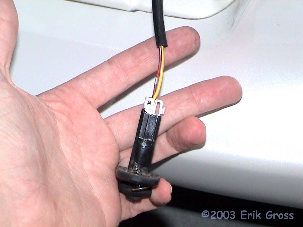
- The OEM Headlight/Foglight Automatic Shutoff Unit senses a ground (0V) pulse on one of its input wires to determine that the driver's door has opened. This causes the auto-shutoff circuit to interrupt the headlight circuit. Thus, after the ignition is off, causing a ground pulse on this input wire will make the auto-shutoff unit to respond as if the driver's door was opened.
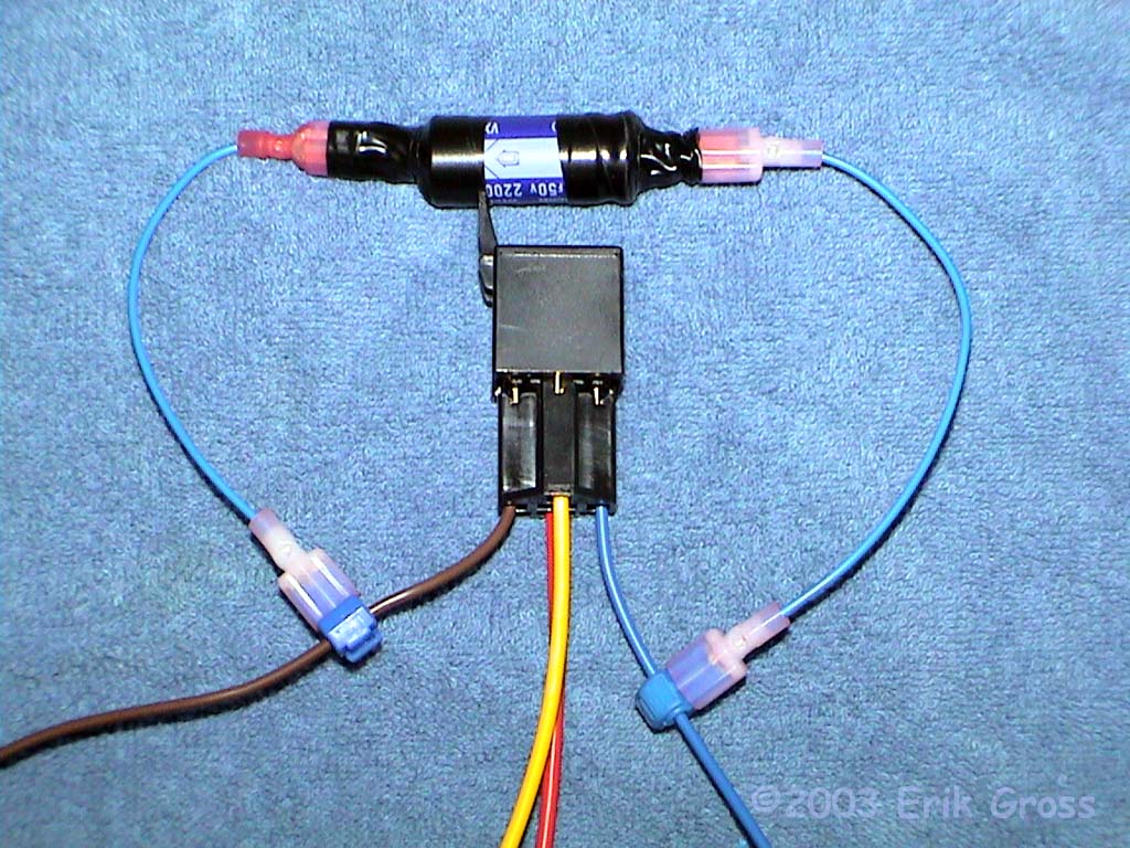
- The purpose of the circuits below is to cause a ground pulse on the door switch wire at some point after the Turbo Timer has turned off the ignition. The circuits are also designed to be some of the simplest/cheapest circuits so that most anyone could build and install them from parts available at a local electronics store.
- If you are considering designing your own circuit to interact with the OEM Auto-Shutoff circuit: I found that a 0.25s ground pulse is sufficient to trigger the headlight shutoff, but a 0.02s pulse is not. Those were the only two values I tried, since I was happy with the 0.25s pulse
How Long Will It Take Me To Do This?
- If you're familiar with electronics and have poked around your car a bit, then it'll probably take you 30 minutes.
- If you're a total newbie, plan on an hour or so.
Anything I Should Do Prior To Attempting This Procedure?
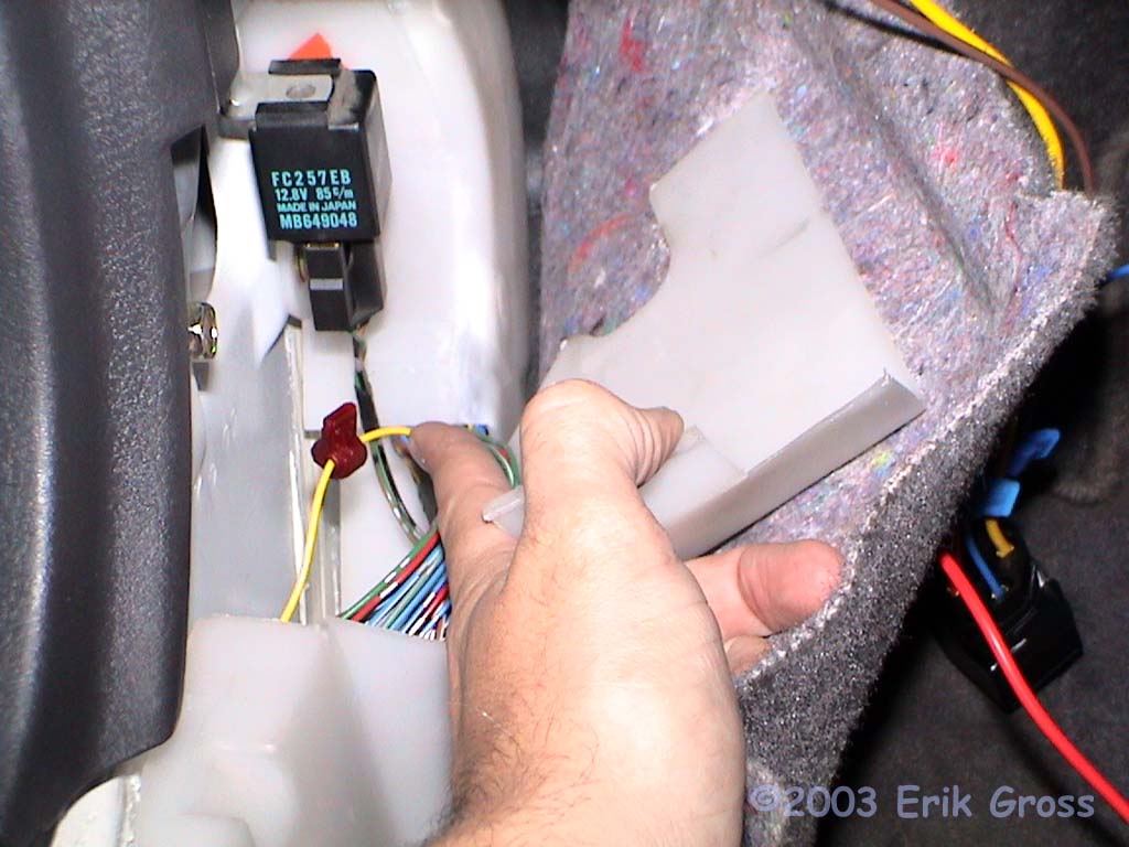
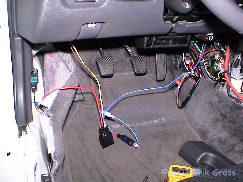
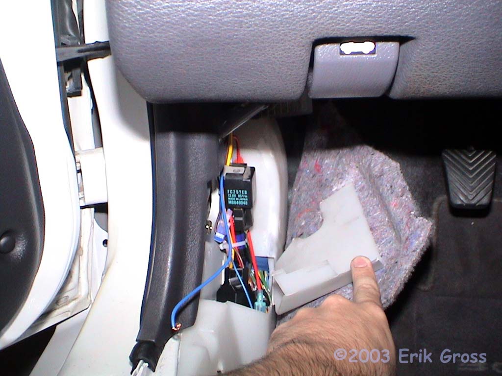
- Remove the driver's side interior scuff plate and the plastic trim that surrounds the trunk and fuel filler door levers. This is probably not completely necessary if you have small hands and a good light, but it takes all of 2 minutes and it makes things a lot easier.
What Mitsubishi Parts Will I Need?
- None.
What Other Parts Will I Need?
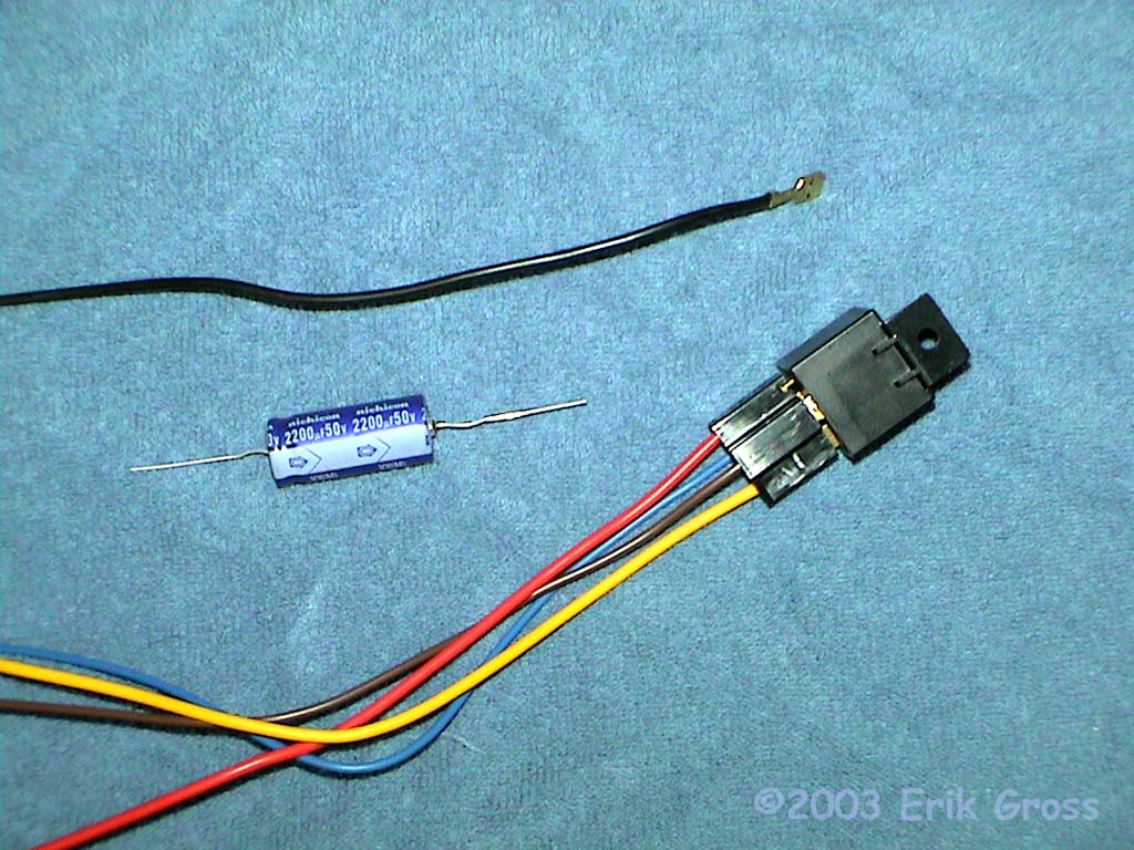
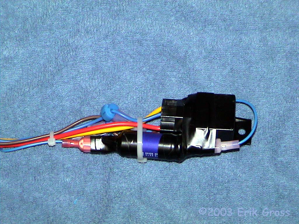
- (1) SPST [or SPDT] 30A 12V Automotive Relay
- (1) SPDT Relay Harness [optional]
- (1) 2200uF Capacitor
- (2) 14-18ga (blue) T-tap
- (1) 18-22ga (red) T-tap
- (1) 10-12ga (Yellow) 3/8" Partially-insulated Crimp-on Ring Terminal
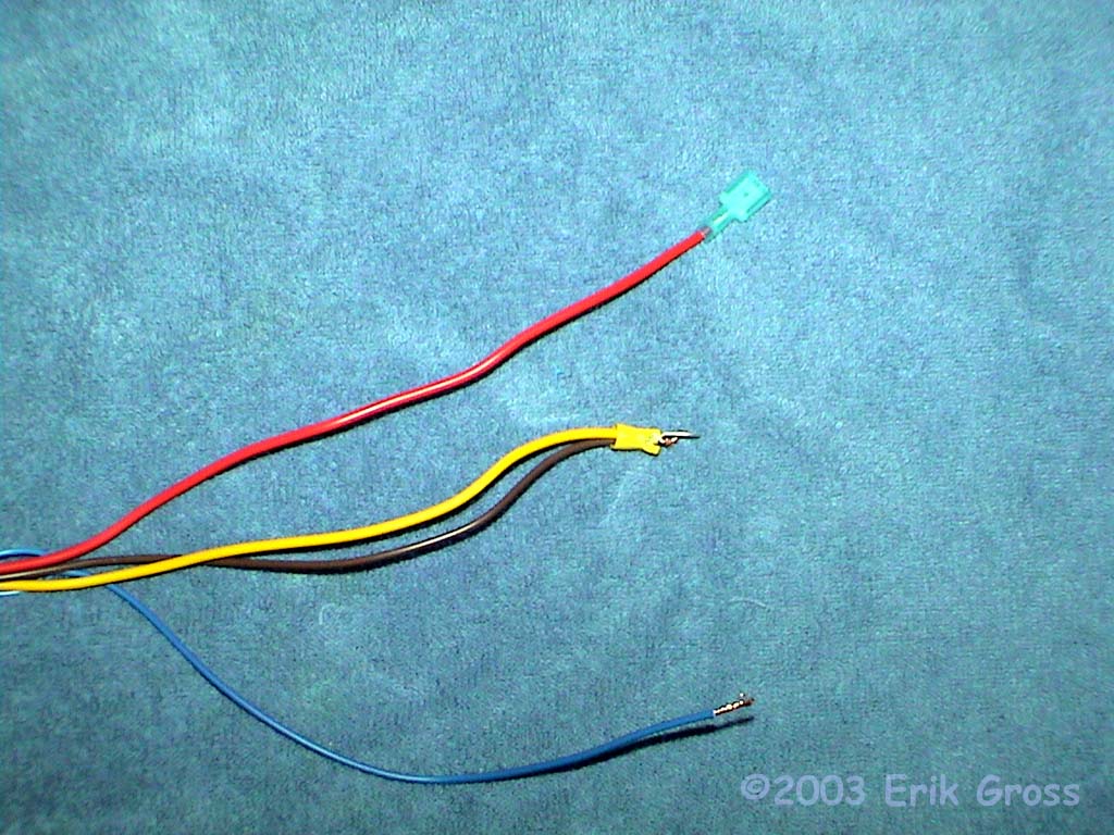
- (2) 14-16ga (Blue) Fully-insulated Male Crimp-on Quick-Disconnect Terminals
- (1) 14-16ga (Blue) Fully-insulated Female Crimp-on Quick-Disconnect Terminals
- (2) 18-22ga (Red) Fully Insulated Male Quick Disconnect Fitting
- (2) 18-22ga (Red) Fully Insulated Female Quick Disconnect Fitting
- 18ga Wire (Blue)
- 18ga Wire (Black)
- Electrical Tape
- Zip Ties
Where Can I Get the Stuff To Do This?
| Part | Company/Contact | Part Number | |
|---|---|---|---|
|
|
Relay | Hosfelt Electronics | 45-287 |
|
|
Relay Harness | Hosfelt Electronics | 21-193 |
|
|
2200uF Electrolytic Capacitor | Radio Shack | 272-1048 |
|
|
14-18ga T-tap | McMaster-Carr | 69515K24 |
|
|
18-22ga T-tap | McMaster-Carr | 69515K23 |
|
|
10-12ga (Yellow) 3/8" Insulated Ring Terminal | McMaster-Carr | 7113K375 |
|
|
14-16ga (Blue) Male Quick-Disconnect Terminals | McMaster-Carr | 7243K22 |
|
|
14-16ga (Blue) Female Quick-Disconnect Terminals | McMaster-Carr | 7243K21 |
|
|
18-22ga (Red) Male Quick-Disconnect Terminals | McMaster-Carr | 7243K12 |
|
|
18-22ga (Red) Female Quick-Disconnect Terminals | McMaster-Carr | 7243K11 |
|
|
18ga Wire (Blue) | McMaster-Carr | 69835K754 |
|
|
18ga Wire (Black) | McMaster-Carr | 69835K351 |
|
|
Electrical Tape, Zip Ties |
Home Depot, Auto Parts Stores |
N/A |
What Tools May/Will I Need?
- #2 Phillips Screwdriver
- Crimping Tool
- Wire Cutters
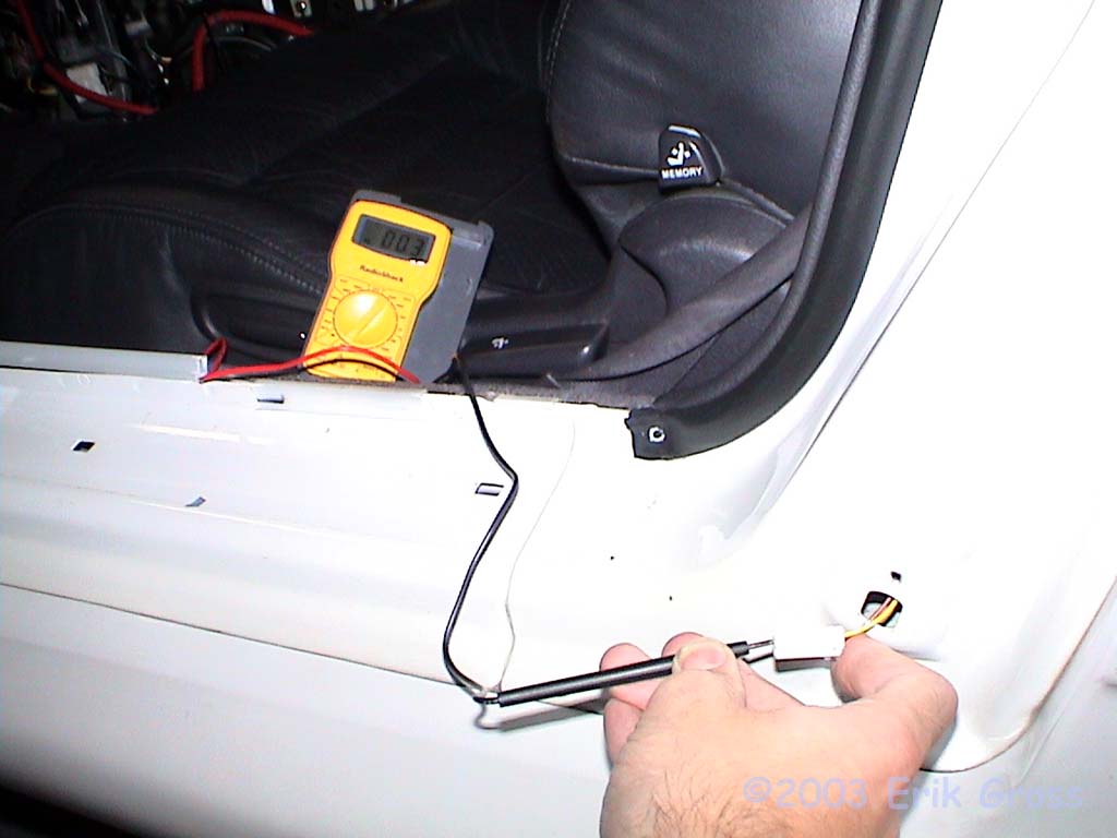
- Multimeter or Continuity Tester
- Crimping Tool